This issue was discussed in the early days of this project, but having seen a Hunter with a pedal / servo alignment problem causing significant stress in the servo internally, I felt it would be a good idea to offer the following advice.
To those who have "Seen it, done it, dealt with it" - well done!
To those who may not, or have not, it might be worth checking, and avoiding.
Copy of general advice email issued to all my contacts who gave me email addresses:
Dual 7" Servo Installation Advice.
Dear All
One of our Dual servo adopters has come across a problem with the installation of his Dual 7" servo. It may possibly have contributed to its failure. Even if not, I would like to pass on the scenario for you to check, and avoid in your installation.
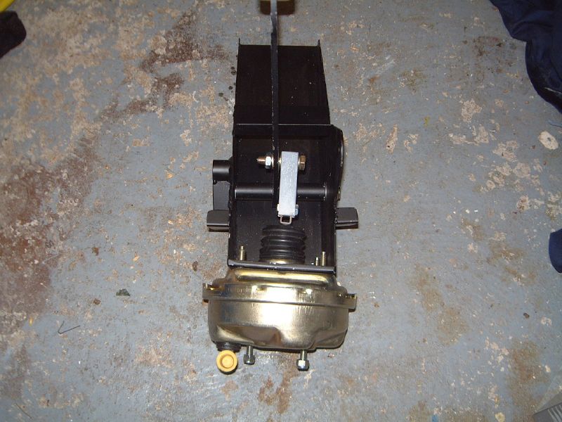
The current Marlin pedal box has been designed not to have the brake pedal axis at right angles to the push rod of the servo - see below (and the same will apply to the Dual 7" servo). In later models the pedal box has an angled bulk head face in the engine bay for the servo to attach to, whilst in earlier Cabrios, the pedal box face was parallel to the pedal, but then the servo was installed at an angle by adding 2-3 washers between the pedal box and the servo on the offside studs only. This slanted the servo/master cylinder in towards the engine front, and away from the body side panel.
The effect of this angle between brake pedal axis and servo is important, and should not be ignored.
Although the new servo has an input pushrod which has some degree of flexibility in its angle - you can test it on your own servo by pressing it from side to side - it is also important that the clevis can rotate ('wriggle') on the pedal bolt sufficiently for it to align in parallel with the input push rod of the servo thereby avoiding any side pressure on the servo.
In the early Hunter installation which has run into a problem, the brake pedal has had the bolt welded in to the pedal - making it a rigid angle. The owner then fitted the clevis (which was a tight fit to the bolt), and included a nut between the two clevis legs. He then fitted a nyloc nut done up reasonably tightly. The overall effect of this installation was that the clevis was held rigidly at 90 degrees to the pedal, and was not able to rotate (wriggle) latterally to line up in parallel with the input shaft of the servo. When the servo was bolted to the pedal box tightly, this rigidity caused a significant side-ways pressure to be exerted on the servo end of the pushrod. This can not be good, and could lead to premature failure of the servo internal workings.
This scenario is easy to avoid - open up the two holes of the clevis with a 10mm drill bit before fitting - preferably as an oval, allowing the clevis to rotate laterally on the pedal until it lines up in parallel with the servo input shaft. The degree of ovality need not be great, and can easily be judged by offering the clevis only to the pedal bolt and checking before opening up further until it can be rotated to parallel with the line of the pushrod.
I would suggest you do not fit a solid spacer (nut) between the clevis forks.
Finally fit a nyloc nut, ensuring the thread protrudes through the nut, but is not tightened hard against the clevis.
An example of this can be seen below.
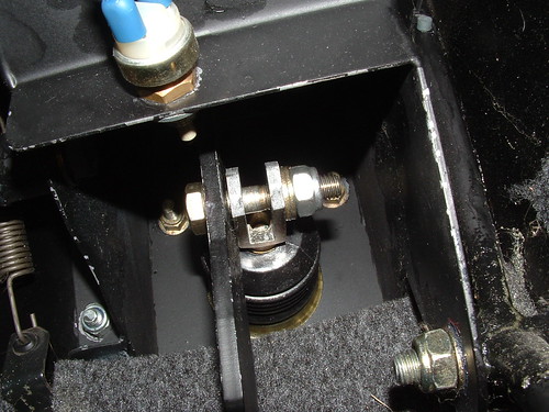
If you look carefully at the above photo, the clevis side is not parallel with the side face of the brake pedal - instead it has had the two holes elongated and been allowed to take up the line (parallel) of the servo push rod, thereby avoiding placing any side forces in to the servo. Also the nyloc has not been done up too tight to force the clevis over to the pedal side.
For those whose pedals have a hole,and/or the clevis lines up to fit around the pedal, rather than alongside, the principles to apply are the same: the final connection of the pedal to the clevis, must allow it to rotate laterally to line up in parallel to the servo input shaft.

I have modified my pedal arrangement, but the priciple can be seen above. The hole in the pedal has been made oval allowing the pin to rotate laterally and line up with the holes in the clevis without introducing strain.
Although this may sound complicated when you read it, when you look at the attached photos in detail, and have a look at your own installation, you will see the alignment issue, and hopefully understand what is required to ensure a safe long term workable solution
If anyone still has any concerns, please do give me a call, and I will try to talk you through the issue.
To those of you that have recognised this issue already and dealt with it, I apologise for teaching Granny to suck eggs! - but as the old adage goes " Better safe than sorry".
For anyone who does not like the idea of making the clevis holes oval with a 10mm drill bit, a rose joint provides the perfect solution allowing the correct angle at all times. These are not expensive, and can be fitted to the pedal bolt tightly without issue. You will require a female thread 3/8" UNF, as below.

Kind regards to all
Mike