Are you madabout kit cars      
 "We've Got Kit Cars Covered" Information about Madabout-Kitcars.com Contact Madabout-Kitcars.com         Home of UK kit cars - madabout-kitcars.com Various kit car write ups All the latest kit car news Kit car related and general discussion

Search
Manufacturers
Kit Cars
Kit Car Data sheets
Picture Gallery
SVA Knowledgebase
Clubs & Communities
Build cost estimator
Kit cars for sale
Knowledge Base 
KitcarUSA.com
Classic-Kitcars.com
 

Go Back   Madabout Kitcars Forum > Mad Build Area > Tribute Automotive Builds

Tribute Automotive Builds Discuss your Tribute kit build

Reply
 
Thread Tools Display Modes
  #21  
Old 18th November 2017, 15:12
WorldClassAccident WorldClassAccident is offline
Senior Member
 
Join Date: Nov 2011
Posts: 3,558
WorldClassAccident is on a distinguished road
Default

Boot latch

20171118_143009 by WCA!, on Flickr


Boot catch and 'mechanical solenoid' boot opener
20171118_143020 by WCA!, on Flickr
Reply With Quote
  #22  
Old 19th November 2017, 07:06
JoeB JoeB is offline
Member
 
Join Date: Nov 2017
Location: Coventry
Posts: 36
JoeB is on a distinguished road
Default

Thanks for the photos WCA! I was hoping to set the latch up on mine something similar to yours although I was hoping to have the boot release on an electrical solenoid so I can still open the boot off the key fob. The solenoid would need to be located in the boot lid itself. The puzzling part is that there does not seem to be enough space in the fibreglass boot lid for the lock mechanism and the solenoid.

I may try and swap the positions of the lock and striker and make a frame to support the lock to see how I get on.
Reply With Quote
  #23  
Old 19th November 2017, 08:04
Barber's Avatar
Barber Barber is offline
Senior Member
 
Join Date: Apr 2016
Location: Camberley
Posts: 972
Barber is on a distinguished road
Default

Swapping the catch and striker is what Chris did on the 275, and it what I have requested for my Z3gato.
Reply With Quote
  #24  
Old 19th November 2017, 08:54
WorldClassAccident WorldClassAccident is offline
Senior Member
 
Join Date: Nov 2011
Posts: 3,558
WorldClassAccident is on a distinguished road
Default

I think I still have a remote operated latch puller in the garage left over from a failed attempt to have no door handles.

Basically you press the button and it pulls a piston with a hook on it. You connect some cable to the hook and then route the cable to the latch. Press the button and the hook pulls the cable, the cable pulls the latch and the door pops open. This give you some flexibility on where the latch and stricker are placed

If you are interested I can try and find it and post some pictures.
Reply With Quote
  #25  
Old 19th November 2017, 08:55
JoeB JoeB is offline
Member
 
Join Date: Nov 2017
Location: Coventry
Posts: 36
JoeB is on a distinguished road
Default

I think I may try doing that then I might still be able to use a solenoid to trigger the lock.

I thought I would also put up some more progress on the dashboard that I have got done over the last few days.

Borrowing a photo from Geoff's build, this is what the dashboard looked like when it first arrived from tribute.


With the dash for my car I wanted to put vents in where the original factory vents sat to maintain the heater functionality in the car. I found some vents that would work that had a more classic look to suit the look of the car so I had to reshape the dash a little so they looked right. Once I had put the vents in I cut out the rest of the holes in the dash.


I also managed to get chance to work on the new dial faces ready for when I put the dials together.

Reply With Quote
  #26  
Old 19th November 2017, 09:01
Jaguartvr's Avatar
Jaguartvr Jaguartvr is offline
Senior Member
 
Join Date: Jan 2014
Location: Egham, Surrey
Posts: 1,780
Jaguartvr is on a distinguished road
Default

Watching this with great interest. Please post all the details for me to blag at a later date.
Looking at the central holes you have obviosly left a space on the right for a key switch or start button. If you go for the key switch you will find they rub on the dash and will scratch it very quickly. A starter button is a better option.
What instruments are you going to use and where did you get the dials from?
Reply With Quote
  #27  
Old 19th November 2017, 09:28
JoeB JoeB is offline
Member
 
Join Date: Nov 2017
Location: Coventry
Posts: 36
JoeB is on a distinguished road
Default

I will do
It will probably be a push button at some point to control some aspect of the car.

I liked Geoff's idea of some kind of hybrid instruments so I have followed a similar route with a little bit of a change. I couldn't find any older dial casings to use that I could get for a reasonable price so I looked into making my own.

Taking some stock material and fabricating some dial cases. The material started off as some 5 inch 6mm wall aluminium pipe.


Plus a 5 inch dial trim ring for £4 on eBay and some left of 3mm acrylic sheet from my rear lights resulting in some dial casings.


The dial internals will be from the original z3 instrument cluster rewired so that they are on plugs. The odometer will also be removed from the original cluster and placed in its own binical between the two dials. The warning lights will be relocated to here too.
Reply With Quote
  #28  
Old 19th November 2017, 17:49
casamolino casamolino is offline
Senior Member
 
Join Date: Dec 2012
Posts: 432
casamolino is on a distinguished road
Default

Evening Joe that is a cracking piece of work to make those bespoke dial clusters , i would think you could make a few for others , are you going to un-solder the odometer from the instrument cluster? I installed the complete instrument cluster in such a position that my odometer can still be seen behind my new centre console , Geoff .
Reply With Quote
  #29  
Old 20th November 2017, 15:04
JoeB JoeB is offline
Member
 
Join Date: Nov 2017
Location: Coventry
Posts: 36
JoeB is on a distinguished road
Default

Thanks Geoff,

At first it was a little complicated as trying to work out how I'd fit all the components into the housing (motors, leds, needles, etc) was a bit tough although once I'd figured out how the dials would be assembled and fitted it was quite simple. Making some more would be easier as now I know what works and what doesn't!

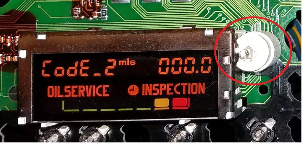
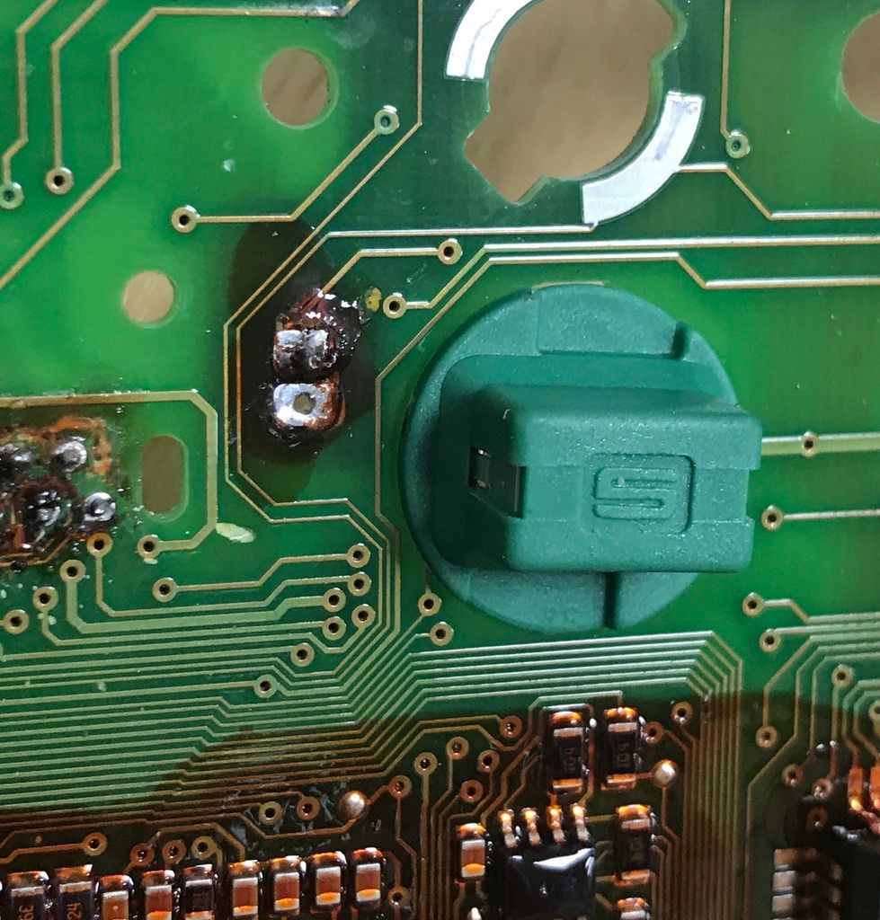
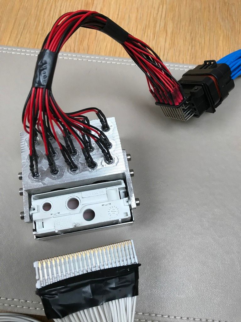
The Odometer itself is actually a socket! The circuit board has an integrated plug and the two fit together. What is a little strange is the light that is housed in the odometer is not on a plug and permanently attached to the circuit board. This prevents the odometer and the circuit board from coming apart and makes me wonder why have it on a plug and socket if you cannot remove it without and soldering iron?!

I have un-soldered the plug on the circuit board anyway so I can place the odometer wherever I choose.

Geoff your build has inspired the majority of the things I have undertaken in my own build, including the idea of hybrid dials!

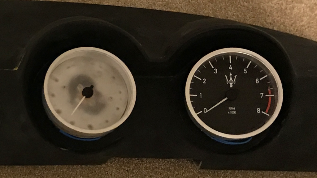
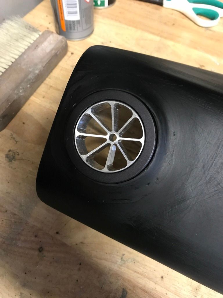
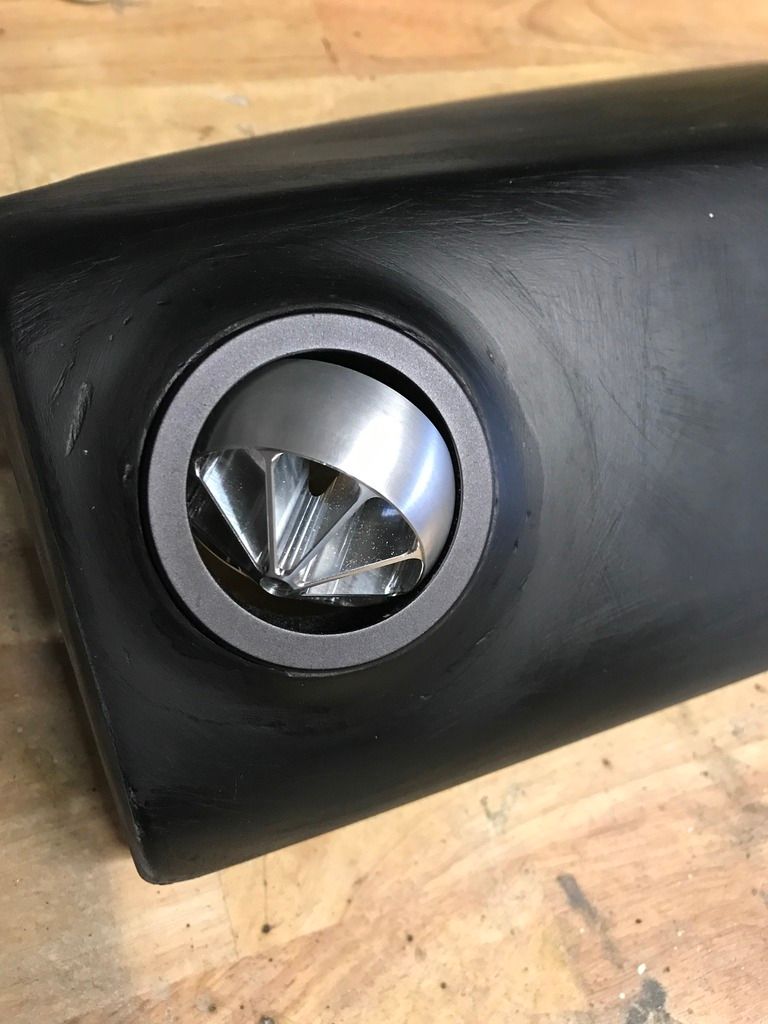
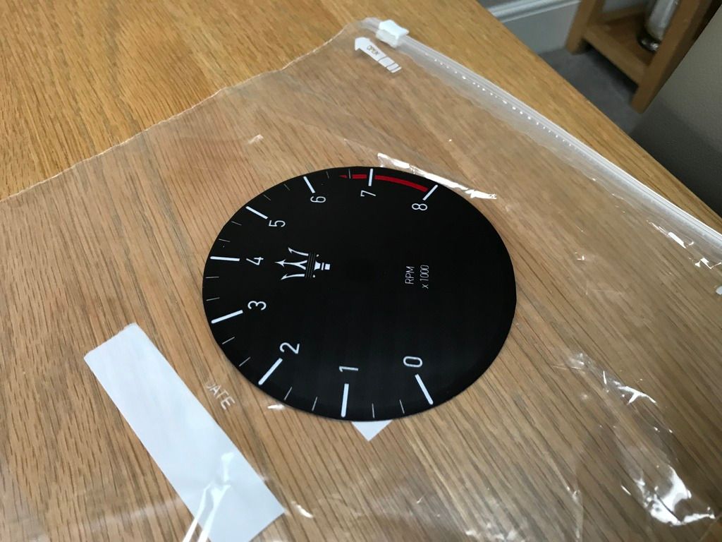
Speaking of the dials, this is what I have come up with so far....

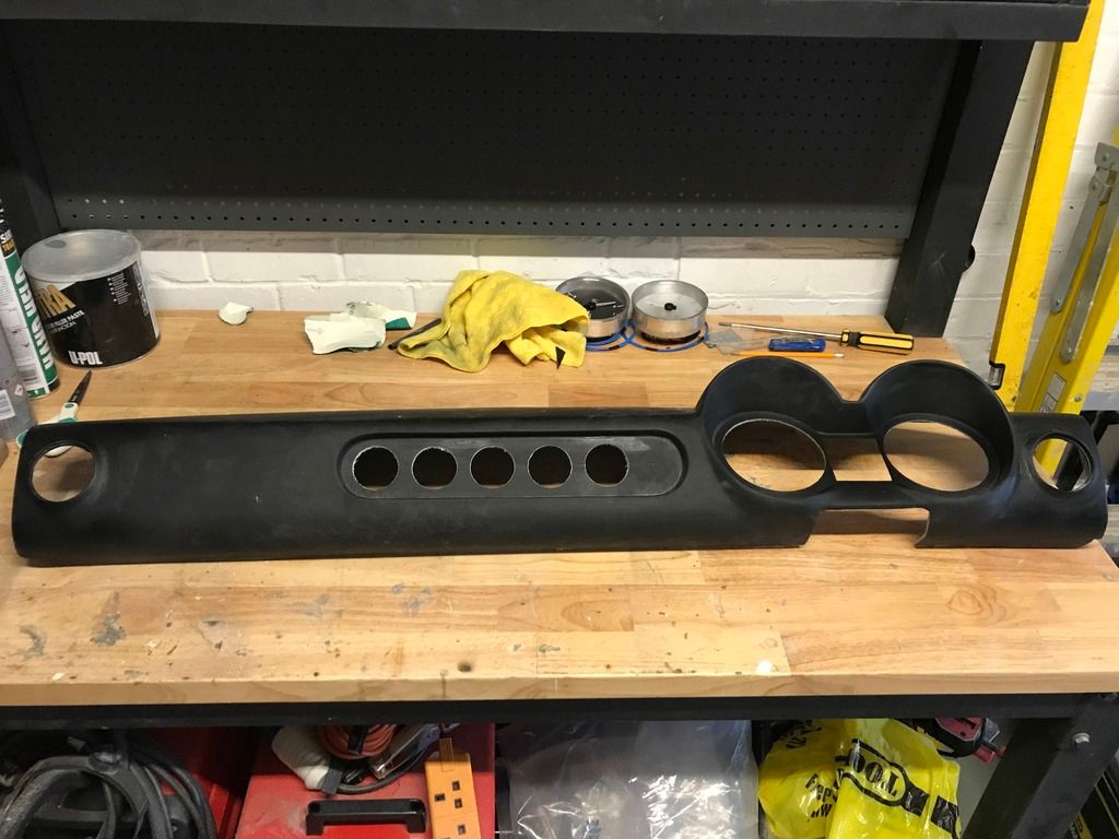
Checking the dials for fit in the dashboard (Dial face is just a rough version to check sizing)


Once I knew the dials would fit it allowed me to see exactly how much space I had left in the centre for the odometer and warning lights. This is what I came up with at first...


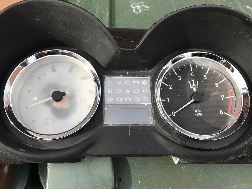
This was a mock up of how I would've liked it to look however this didn't really work for me in the end as I couldn't get everything straightened up or get it to look 'right'. Plus I had to think of a way of getting the warning lights to work.

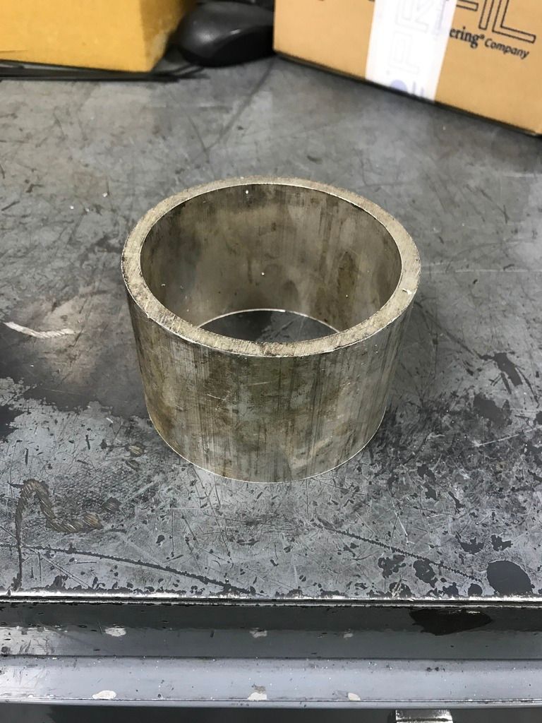
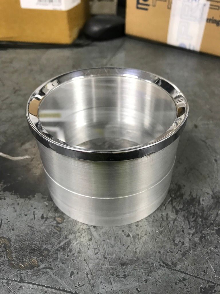
I decided to make up a sort of binnacle to house the odometer and warning lights as it looked neater and better when next to the dials.


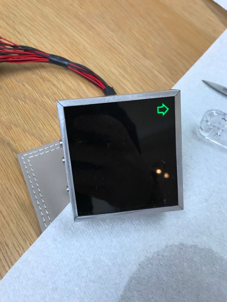
Finally, I took some inspiration from the modern types of gauges you see with blank faces until they light up with ignition. (Defi Gauges) I wanted this type of effect with the odometer and warning lights.


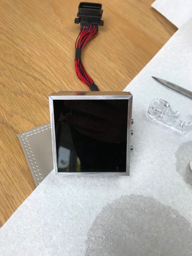
This is achieved using a 30% tint film on the acrylic so that the odometer and warning lights can only be seen when they are on.


Last edited by JoeB; 20th November 2017 at 15:10..
Reply With Quote
  #30  
Old 20th November 2017, 15:36
Jaguartvr's Avatar
Jaguartvr Jaguartvr is offline
Senior Member
 
Join Date: Jan 2014
Location: Egham, Surrey
Posts: 1,780
Jaguartvr is on a distinguished road
Default

Can we have some pictures of the rear. Especially the odometer.
Reply With Quote
  #31  
Old 20th November 2017, 16:17
JoeB JoeB is offline
Member
 
Join Date: Nov 2017
Location: Coventry
Posts: 36
JoeB is on a distinguished road
Default

I am not at home at the moment but I will get a photo of the back of the odometer and lights.

I have got some photos which might shed a bit more light on what I mean with regards to removing the odometer:

This is the light I was referring to that needs to be removed to free up the odometer.


These are the two pins that need to be desoldered to allow the odometer to unplug from the circuit board...
Reply With Quote
  #32  
Old 21st November 2017, 09:49
JoeB JoeB is offline
Member
 
Join Date: Nov 2017
Location: Coventry
Posts: 36
JoeB is on a distinguished road
Default

Jaguartvr here are a few photos of the rear of the new cluster.


The odometer plug has 45 pins that each need to be desoldered from the circuit board and cables putting in for anyone also wanting to move the odometer.
Reply With Quote
  #33  
Old 21st November 2017, 11:59
Jaguartvr's Avatar
Jaguartvr Jaguartvr is offline
Senior Member
 
Join Date: Jan 2014
Location: Egham, Surrey
Posts: 1,780
Jaguartvr is on a distinguished road
Default

How many leads need soldering!

Soldering is not my strong point so this may well be a step too far.
What we need is someone who can supply some kind of exchange plug and play kit.

Now, who's going to volunteer?
Reply With Quote
  #34  
Old 21st November 2017, 12:27
JoeB JoeB is offline
Member
 
Join Date: Nov 2017
Location: Coventry
Posts: 36
JoeB is on a distinguished road
Default

There are 45 pins on the odometer plug, 45 wires to solder to the circuit board plus with the warning lights I've used, 30 wires to be soldered to the LEDs, 30 wires to the plug, 30 wires from the plug to the corresponding places on the circuit board for the warning lights.

Plus 4 more wires for the lights that sit inside the odometer to produce the back light to be connected to the illumination circuit on the circuit board.

98 soldered connections for odometer
Around 120 soldered connections if you have the warning lights on a plug and socket.

Quite a lot of soldering to do this particular task.
Reply With Quote
  #35  
Old 21st November 2017, 12:32
Jaguartvr's Avatar
Jaguartvr Jaguartvr is offline
Senior Member
 
Join Date: Jan 2014
Location: Egham, Surrey
Posts: 1,780
Jaguartvr is on a distinguished road
Default

Fancy doing another one?
Reply With Quote
  #36  
Old 22nd November 2017, 12:22
JoeB JoeB is offline
Member
 
Join Date: Nov 2017
Location: Coventry
Posts: 36
JoeB is on a distinguished road
Default

It a monster task to complete but I could probably do another one if needed.
An easier method of doing it would be to get a spare instrument cluster for the Z3 and dismantle it for parts (odometer housing and plug).

You could then use the parts salvaged to create something like an extension lead to plug into your existing odometer and instruments? This would be a little easier to make as it would not have to be as precise.
Reply With Quote
  #37  
Old 22nd November 2017, 12:26
Jaguartvr's Avatar
Jaguartvr Jaguartvr is offline
Senior Member
 
Join Date: Jan 2014
Location: Egham, Surrey
Posts: 1,780
Jaguartvr is on a distinguished road
Default

I just happen to have a spare dash on my table!
Reply With Quote
  #38  
Old 22nd November 2017, 15:49
redratbike's Avatar
redratbike redratbike is offline
Senior Member
 
Join Date: Sep 2011
Posts: 1,446
redratbike is on a distinguished road
Default

Quote:
Originally Posted by Jaguartvr View Post
I just happen to have a spare dash on my table!
as you do
Reply With Quote
  #39  
Old 22nd November 2017, 16:06
JoeB JoeB is offline
Member
 
Join Date: Nov 2017
Location: Coventry
Posts: 36
JoeB is on a distinguished road
Default

Well that would make the job a lot easier!!

If soldering is not really your thing, you could actually run a hacksaw blade between the plug and spare circuit board to separate them. Then just solder onto the remaining pins left of the plug.

It wouldn't need to be as accurate and would be a bit easier to solder on to once the plug is free from the circuit board.
Reply With Quote
  #40  
Old 22nd November 2017, 16:09
JoeB JoeB is offline
Member
 
Join Date: Nov 2017
Location: Coventry
Posts: 36
JoeB is on a distinguished road
Default

Just wondering if anyone with a Z300S or 250 SWB had considered any type of forced induction on their car? Either turbo charging or super charging?

I know many people prefer using the 6 cylinder engines for their builds so there are a few potential options but I just wondered if anyone had thought about it, or better yet done it?
Reply With Quote
Reply


Currently Active Users Viewing This Thread: 1 (0 members and 1 guests)
 
Thread Tools
Display Modes

Posting Rules
You may not post new threads
You may not post replies
You may not post attachments
You may not edit your posts

BB code is On
Smilies are On
[IMG] code is On
HTML code is Off

Forum Jump


All times are GMT +0. The time now is 17:30.

copyright © madabout-kitcars.com 2000-2024
terms and conditions | privacy policy