|
|
| Marlin Sportster, Cabrio, Berlinetta and Roadster builds Enthused or Confused about your vintage Marlin build? Ask away here or show off your build. |

10th March 2015, 21:16
|
 |
Senior Member
Enthusiast
|
|
Join Date: Mar 2005
Posts: 3,077
|
|

Quote:
Originally Posted by 8 Valve Ed

Thanks for the compliment on the pictures, I try to take some which may help others understand there are many roads to Rome. I am overcome with the bonnet, it was so easy to roll, I am sure with more experience and a bit more patience I could have made a better job but I think it will hold together!
I have finished fitting the bonnet, I still have to set the rivets but I am waiting until the w/e when I have some more hands to help. I think I will need a lot of help to set the rivets, 23 each side for the central hinge, plus a similar number in the engine side panels. I am toying with the idea of peening them with my air hammer. I dug it out last night and it appears to be rusted up, the trigger is seized so I think some thin oil and a bit of encouragement may be needed.
|
Your bonnets are as good as (or better) than the Marlin factory supplied bonnets that still need some persuasion to fit and need to be cut to size to fit. You are right to be proud of what you have produced 
I fitted my bonnets with SS nuts and bolts which are real pain to fit but is does mean you can dismantle for painting, etc.
But rivets will certainly look more authentic and 'period' if thats what you are aiming for. (...and don't forget the angle stiffners on the underside)
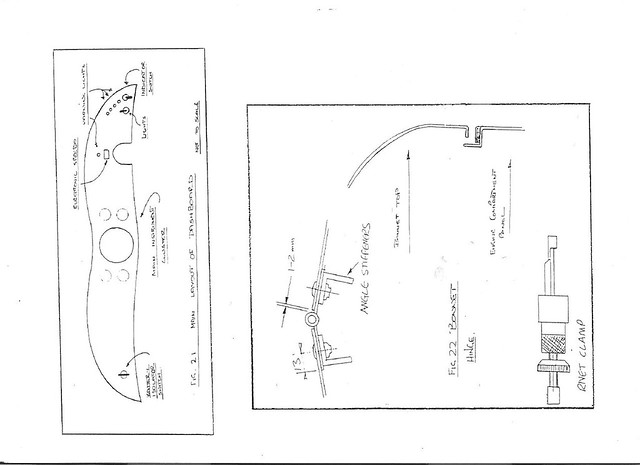 Bonnet fitting 2 Bonnet fitting 2 by marlinpeter, on Flickr
...peter

|
10th March 2015, 22:27
|
|
Senior Member
|
|
Join Date: Dec 2013
Location: Sunny Cumbria
Posts: 470
|
|
Thank's for the kind words I was offered a bonnet when I collected the car by somebody else but I decided to change the scuttle so it had a radius rather than a ridge so in fact I would have had to make my own anyway.
I formed the (single) curves on the English wheel by putting a rubber band, an old inner tube, over the top wheel which caused the lower wheel to form the curve in the panel without crushing the metal and making it a double curve.
Also thank you for showing me that drawing, confirms my construction method. What is that "Rivet clamp" in the lower right of the drawing?
What I had been more worried about was how to make the transition from radius at the back, to straight or flat at the front. In fact it was so easy I could have kicked myself.
Yes, I have made some reinforcing angles by having some folded from an off cut of the bonnet sheet, 1.5mm, then I doubled the down leg by rolling the layers together, to form a double skin for the vertical leg. The bonnet is very rigid when pressed in the centre of the hinge, although I'm not sure it would support a scantly clad model for a photo shoot!!! ;-) Maybe, once it's all riveted up?
Will try for some more pix tomorrow, I'm dead beat for today.
Last edited by 8 Valve Ed; 10th March 2015 at 22:29..
|
11th March 2015, 07:24
|
 |
Senior Member
Enthusiast
|
|
Join Date: Sep 2004
Posts: 1,891
|
|
Quote:
Originally Posted by 8 Valve Ed
What is that "Rivet clamp" in the lower right of the drawing?
|
The rivet clamps come from the aerospace industry and are used to temporarily clamp panels together during the riveting process. They simply fit through the rivet holes. There are two types - sprung and threaded. The threaded ones are best although the sprung ones are quicker to fit and adequate under most conditions. There are always plenty for sale on ebay - try searching for clico (brand name) or skin pins. (You can get some weird results from skin pins though ;-) ) I've used (am still using) getting on for a hundred during the Pembleton construction.
Cheers, Robin |
11th March 2015, 08:14
|
|
Senior Member
|
|
Join Date: Dec 2013
Location: Sunny Cumbria
Posts: 470
|
|
Thanks Robin, I was aware of Clicos, never met one in the flesh though.
I can imagine they can be very useful, and once you have used them, indispensable! I get by with a few clamps and bit's of wood, maybe the odd unset rivet but generally I don't use rivets much, I tend to assemble with stainless capscrews and nuts, with washers as appropriate.
There was a lovely blue Cabrio (I'm sure you know the one) not that far from here which had stainless dome headed capscrews securing the hinges. Beautiful and really nicely installed, BUT the screws dominated the panels and became a distraction, constantly drawing the eye. That's why I am going for less noticeable rivets which will be painted with the panel. They also help with the illusion of the originality.
OK, I have been thinking... Dangerous I know, I have been looking at the underside of the bonnet, and what lies below. I can imagine that with our normal weather there will be a problem with rain water dripping through the hinges onto the engine, carbs and perhaps more importantly, the plug leads/distributer. Last night I was contemplating the annoyance of having to cover the engine whenever I leave the car out in the rain, the rain here is full of salt and sand too. Neither of which I really want all over my engine etc.
Well I have come up with what I consider may be a solution, would welcome comments please...
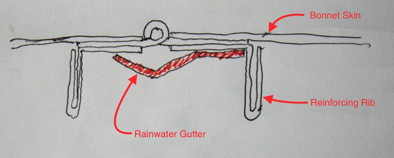
This would be riveted to the underside of ONE side of the bonnet, probably the n/s, that way either side can be opened and it should deflect the water to drip down in front of the engine, or possibly behind if the car is parked facing uphill.
Off out for another day of excitement and joy! ;-))
|
11th March 2015, 21:28
|
|
Senior Member
|
|
Join Date: Dec 2013
Location: Sunny Cumbria
Posts: 470
|
|
Another productive day, Done some more 'those jobs' I have been putting off.
I needed to do a couple of little welding jobs, the battery box needed welding up and I needed to weld a little patch onto one of the floor plates. Ordinarily a little welding would just be a matter of turning the MIG on and a few seconds later it would be done but these two items are aluminium. Currently my only way of welding aluminium is to gas weld it. Getting the gear out was the biggest job, I couldn't find the Oxygen cylinder, Michael had tidied up and put it in a corner where I couldn't see it. I have a very special visor for welding aluminium which allows you to see through the flare which is created by the flux. I had to mix the flux and set the gas pressures. I am no expert in welding aluminium with gas, however, though I say it myself I didn't do a bad job, by my standards anyway.
When I changed to a manual gearbox I had already cut the floor plates to fit the profile of the wider auto gearbox. So I needed to weld back in a small patch to fill the gap.
The battery box is made from 3mm aluminium, I folded it with the English wheel but it still needed welding at the four corners, mainly to prevent any slight spillage of acid spreading across the boot.
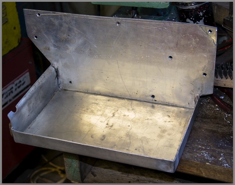
I struggled with the battery box a bit but I trimmed the back flange back to give me a corner seam and it welded up a treat.
Since then I have final fitted the battery box and final fitted the rear tub. The poor tub must be dizzy! It has been on and off that car a hundred times. Hopefully that's the last time I will fit it this side of the MOT. This means I can address the fuel filler and start wiring up the back of the car.
A friend has agreed to fold the rainwater channel for me, it's just too tricky to make a really neat job by hand, it will take him a few seconds to crop the metal and put two straight folds in it. I know it's under the bonnet but I am expecting to have the bonnet open from time to time and I want it to look neat.
|
12th March 2015, 19:07
|
|
Senior Member
|
|
Join Date: Dec 2013
Location: Sunny Cumbria
Posts: 470
|
|
More of 'those jobs' today. I tackled the coolant bleed pipe from the manifold into the header tank of the radiator. Hopefully without provoking any more leaks in the radiator. 
I attempting to correct a slight misshaping in the scuttle panel causing the new bonnet not to sit as I would like. I did battle with the fuel tank filler pipe... I won! LOL It was a swine to get lined up, in the end I drilled a 60mm hole where I wanted it and fabricated the pipe as required. I created a tank breather and tie wrapped all the rubber fuel pipes so they don't flap about and so they look a tad neater.
My friend called round to collect the metal to fold the under-hinge gutter for me, he thinks he has some stainless tube which would make a pair of tail pipes for my exhaust and some aluminium sheet to form the back bulkhead and seat back for the (occasional) back seats.
We move on apace!
Tomorrow I am hoping to collect a pair of air filters so I can start the engine and run it for longer than a few minutes... I can't set the ignition or the mixture until that's sorted. I also need to be able to feel the clutch because I am not sure it's clearing properly. I may need to alter the master cylinder.
According to my research the Rover SD1 has a 7/8" slave cylinder and a 5/8" master cylinder. It's an original slave cylinder but the master is from a Marina, which *should* be 5/8" Which should all work... but there is quite a bit of slack movement at the beginning of the clutch lever stroke which may be the cause. I found by pumping the clutch pedal I could engage gear, it MAY clear itself with use, but it may not... Until I can start the engine and run it properly I can't tell. It may just need a kit of seals for the master cylinder. I checked out Rimmers for an SD1 master cylinder and it was top side of £70, with VAT and shipping it will probably be close to £100 
Off out now just to tidy up and check stuff over.
Last edited by 8 Valve Ed; 12th March 2015 at 19:09..
Reason: A reluctant smilie!
|
15th March 2015, 06:09
|
|
Senior Member
|
|
Join Date: Dec 2013
Location: Sunny Cumbria
Posts: 470
|
|
Passed the 90% milestone
Yesterday we passed the 90% milestone, Michael my son has been busy doing lots of little jobs, like painting the fuel filter bracket (black) and painting the underside of the boot lid so I can finally fit the boot lid skin I made a while back...
My friend turned up with lot's of goodies! A sheet of aluminium to form the back bulkhead/rear seat back, my gutter which he has folded perfectly to stop water dripping on the engine, and two lovely pieces of stainless steel tube for the tail pipes. I need to bend them slightly to go under the back axle... That may be a challenge. I do know of a place with a set of power bending rollers, if they have the dies I may get it bent there, otherwise I will have to cut and weld but I don't have any pure argon to TIG them.
My friend is going to fold some thin stainless for me to make the bars for the radiator grill, I don't like the original Marlin supplied, kinked, 2.4mm ally welding rods that need knitting into a mesh.
I have started fitting the front wings, and discovered the supporting brackets are missing. I don't remember them although from the few photographs I have of the car before it was dismantled they were present. In order to push the job forward I have decided to create two fresh brackets.
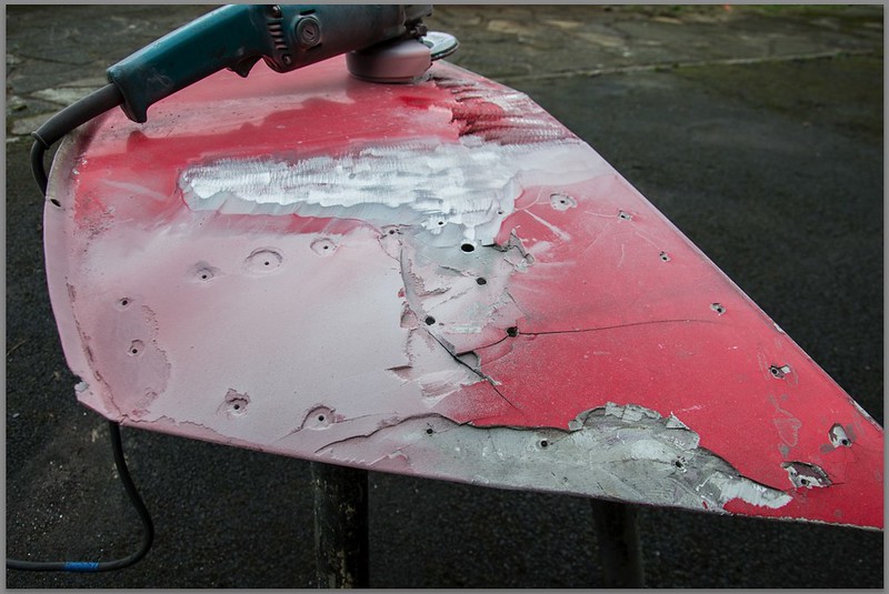
On Friday I tackled the front inner wings. They were in a bad way, the o/s one was battered, both suffered from stress cracking in a crescent above the lamp bar attachment point, also star cracks around the lamp bar bolt holes. I ground off almost 10mm of body filler which a PO had applied in a poor attempt to mask the cracks. Once the filler was off I could see the full extent of the damage. I welded the cracks up as best I could. The aluminium is very thin, it was 16g originally but a PO has ground it heavily to give key for the filler and I ground some more off getting rid of the filler!!! I didn't bother measuring it but it remains no thicker than 1.2mm I am sure. With three passes I managed to weld the cracks reasonably well without blowing any serious holes.
The photographs show a pattern of pop rivet holes, a PO had riveted pieces of steel behind the panel to stiffen it. Apart from the tendency to encourage corrosion, the steel increases the front end weight which is against my principles, I like light and simple, so the steel plates were dumped long ago. Instead, I think I have removed the cause of the cracking by stabilising the inner wings by attaching them to the front subframe, which effectively stops them flapping about.
I used Oxy Acetylene and a silicone TIG welding rod. I find Magnesium tends to crack on cooling. The third pass left the weld pretty flat and nicely malleable with a little fettling it went in the English wheel and worked nicely.
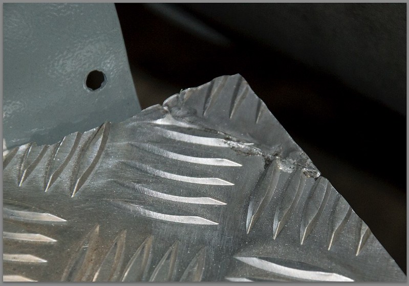
This shows the extent of the damage. The cracks are around the three lamp bar mounting holes, the fourth hole is for the wires. I used a 40 grit flap disk to remove the filler, very effective but also very dusty!
A close up of the cracks:
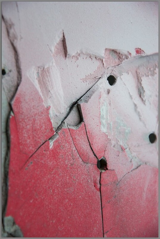
After rough cleaning and removal of the body filler, the main crack was about six inches long.

After welding, not pretty but once fettled it was OK. I also dabbed several of the pop rivet holes but not all I was running short of time.
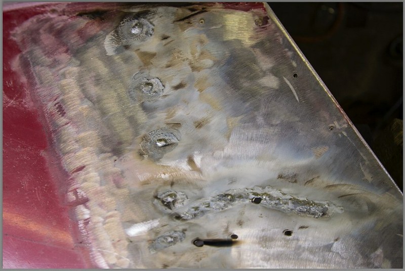
I will take another photo of the welds once the wings are fitted, time was catching up with me so I haven't captured any more images since these but the welds are blended into the panel now, not perfect but pretty sound I think.
Last edited by 8 Valve Ed; 15th March 2015 at 07:22..
Reason: Adding information.
|
15th March 2015, 21:48
|
|
Senior Member
|
|
Join Date: Dec 2013
Location: Sunny Cumbria
Posts: 470
|
|
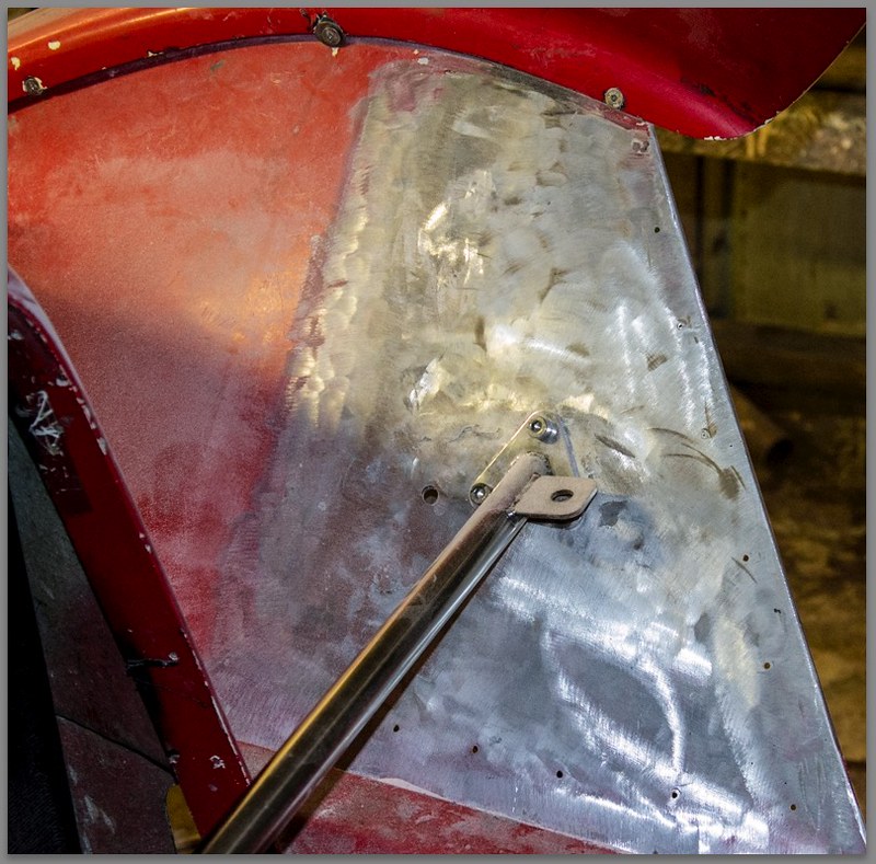
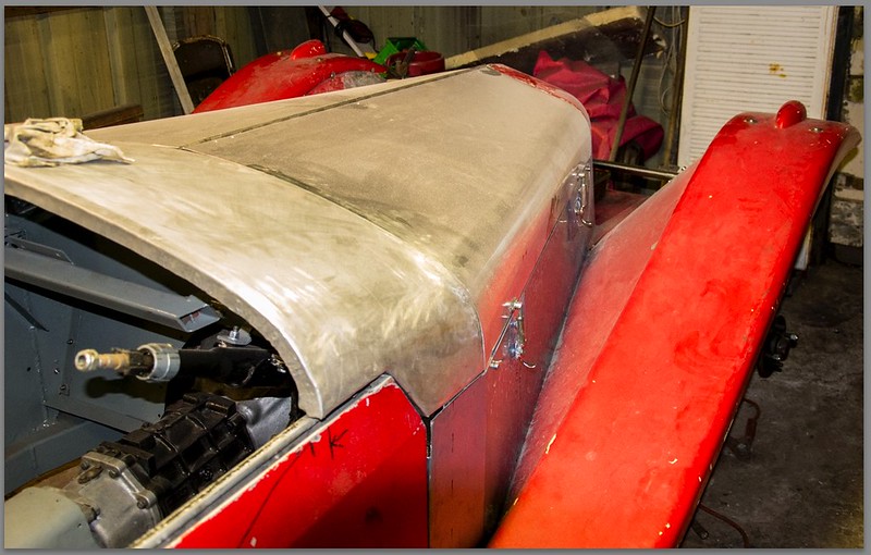
The front wings are now temp fitted. The inner wing welding seems to be holding OK, I have today made the second wing strut. Has taken some effort, Michael has been filling some redundant holes in the fibreglass and I have had to supervise because he has never done any car fibreglassing before.
I had intended to do the riveting of the engine side panels and the bonnet hinge but I got stuck into the wing support struts and Michael the body filling, I decided to leave the riveting until next week. I may try doing the engine sides myself.
Here are some photographs of todays activities, firstly the near side inner wing. The weld is almost invisible now, it's just above the lamp bar, running right next to the top hole.
This is the off side wing support strut which I made yesterday.
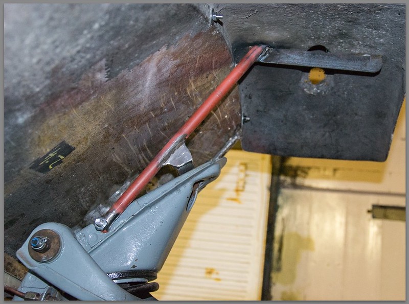
And this is a general view which shows how low the front of the car is.
That's it for now, I can scarcely keep my eyes open... A long day, and a lot done.
# 3047
Last edited by 8 Valve Ed; 16th March 2015 at 07:37..
|
16th March 2015, 20:59
|
|
Senior Member
|
|
Join Date: Dec 2013
Location: Sunny Cumbria
Posts: 470
|
|
A Mixed Day
Rather an up and down day today... When I went out to the car I noticed a pool of oil on the floor around the n/s rear wheel. I had added oil to the axle last week so I thought it might be linked to that but no, it seemed to be coming from the backplate of the brakes, oh-oh. Yes, the rear wheel cylinder had allowed a tank full of brake fluid to leak all over my previously good linings and onto the floor without the car even moving. I removed the wheel cylinder and the bore wasn't good so I decided to visit my local car parts shop. I expected to be able to order the cylinders for later in the week. I was amazed when they rummaged on a shelf and produced a pair of cylinders, just like that! For £15 I think it was a NOS price given I am such a good customer of late. Fortunately I still had a little brake cleaner which I used to hopefully remove most of the brake fluid from the drums and the linings. Unfortunately when I looked in my oils cupboard I don't have any brake fluid... 

And the drum:

I have also made another pair of brackets to mount the lamp bar on. It's now rock solid. However, I feel the headlamps are too far apart, originally some of the Alfa Romeo cars had three lamps, the outer ones closer together than mine are. I have checked out the lighting regs and it seems the edge of the lamp must be no further than 400mm from the side of the car. They are currently 360mm from the side of the car. I propose to cut the tab off the lamp bar and somehow create a pedestal, a vertical tube at the maximum permitted distance from the side and a bit higher , maybe 80mm? This would replicate the original distinctive design of the Alfa layout.

And:

I hope to make the top of the headlamps about level with the top of the radiator cowl. My next challenge in this area is to find a way of simply and securely mounting the headlamps on these pedestals. Now I need my TIG argon gas. Perhaps I can borrow some... Unless I can make the pedestals from aluminium? I do have some tube and a little bit of plate. Will have a rummage in my off-cuts bin tomorrow.
Supper and bed zzzzzzzz.
Last edited by 8 Valve Ed; 16th March 2015 at 21:02..
Reason: Minor edit.
|
17th March 2015, 08:52
|
|
Senior Member
Enthusiast
|
|
Join Date: Jan 2007
Posts: 932
|
|
Quote:
Originally Posted by 8 Valve Ed
However, I feel the headlamps are too far apart, originally some of the Alfa Romeo cars had three lamps, the outer ones closer together than mine are. I have checked out the lighting regs and it seems the edge of the lamp must be no further than 400mm from the side of the car. They are currently 360mm from the side of the car. I propose to cut the tab off the lamp bar and somehow create a pedestal, a vertical tube at the maximum permitted distance from the side and a bit higher , maybe 80mm? This would replicate the original distinctive design of the Alfa layout.
And:
I hope to make the top of the headlamps about level with the top of the radiator cowl. My next challenge in this area is to find a way of simply and securely mounting the headlamps on these pedestals. Now I need my TIG argon gas. Perhaps I can borrow some... Unless I can make the pedestals from aluminium? I do have some tube and a little bit of plate. Will have a rummage in my off-cuts bin tomorrow. |
Be careful extending the height of the headlamp supports - it will increase the turning moment around the headlamp bar enormously and may well lead to vibration shake that is difficult to control .............though you could add stabilizer bars and tie the headlamo shells back to the bonnet top?
|
17th March 2015, 11:25
|
|
Senior Member
|
|
Join Date: Dec 2013
Location: Sunny Cumbria
Posts: 470
|
|
Quote:
Originally Posted by Mike
Be careful extending the height of the headlamp supports - it will increase the turning moment around the headlamp bar enormously and may well lead to vibration shake that is difficult to control .............though you could add stabilizer bars and tie the headlamo shells back to the bonnet top?
|
Hi Mike, I am intending to sit the headlamps on a pillar which extends down to the 'chassis' like the Alfa ones in the Pic above, I think that would be even more solid than the standard lamp bar, although mine is so solid I can stand on it and it doesn't deflect noticeably any more.
However, just for now I have decided to go with the lamp bar as-is although I am going to move the brackets in 40 mm each side. If after a little use, I am happy with the Berlinetta, then I intend to make my own wings, front then rear. At that time I will re-work the headlamp mounts.
Thanks for pointing it out anyway! |
19th March 2015, 08:23
|
|
Senior Member
|
|
Join Date: Dec 2013
Location: Sunny Cumbria
Posts: 470
|
|
Rover P6 3500 wiring diagram?
A bit of a forlorn hope, but does anybody have a wiring diagram for a Rover P6 3500 Mk 2 with the round dials, specifically with the RVC type revcounter?
I have acquired an old instrument panel from one of these cars but I'm unsure of the connections for the rev counter. I don't want to damage it by making the wrong connections.
I have spent some time searching Google but not come up with the goods, perhaps I am using the wrong search terms...
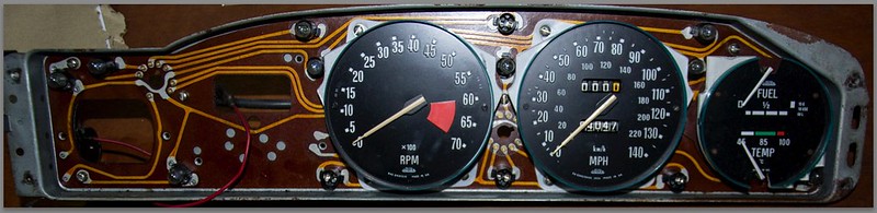
This is the instrument cluster, I am only planning to use the central section with the speedo and rev counter:
This is the front of the rev counter, showing the crucial RVC type at the bottom:
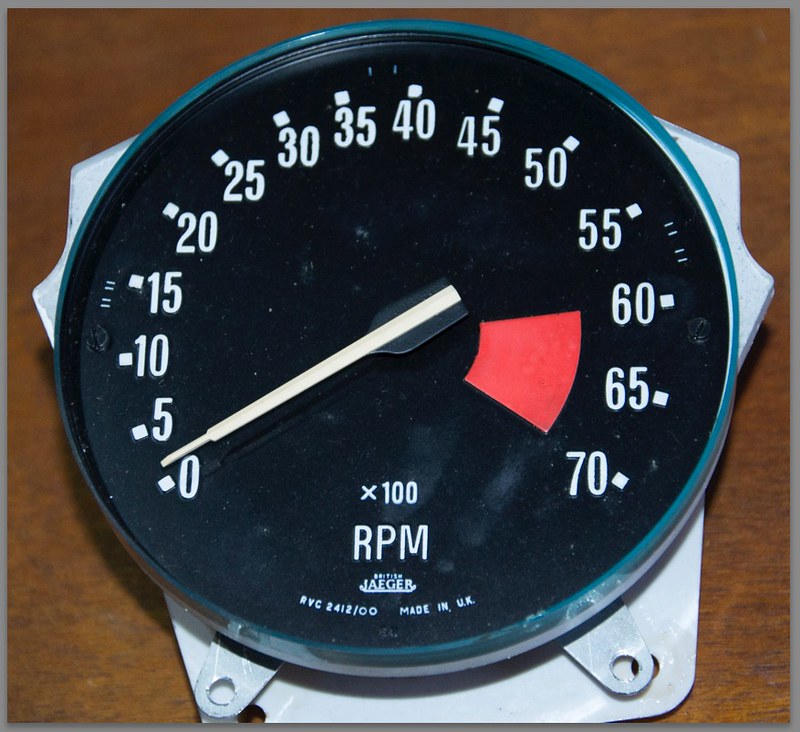
And this is the back of the rev counter showing the connections. I believe the bullet connection should be connected to the - (negative or CB) terminal on the coil and the Lucar or spade terminal to an ignition live wire from the main ignition switch or the other (+) side of the coil. Presumably the instrument body will need earthing too, but that will happen anyway when it's mounted.
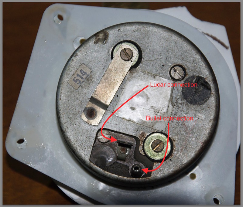
Confirmation or a diagram would be much appreciated. I have an SD1 manual but the ignition is electronic and totally different. I am using points.
|
19th March 2015, 08:32
|
 |
Senior Member
|
|
Join Date: Mar 2013
Location: Gloucester
Posts: 247
|
|
RVC tachos have a bullet connection for the sense wire from the coil -ve and 12V ignition feed to the spade. RVI has two bullets for the loop connection internally.
|
19th March 2015, 08:38
|
|
Senior Member
|
|
Join Date: Mar 2013
Location: Gloucester
Posts: 247
|
|
Common mod to scimitars with rover v8 fitted is to fit the P6 innards into the original Smiths case |
19th March 2015, 08:43
|
|
Senior Member
|
|
Join Date: Dec 2013
Location: Sunny Cumbria
Posts: 470
|
|
WOW!!! Thank you. That is amazing, brilliant, I am so grateful, that has saved me hours. A positive response in nine minutes, you can't beat that! Wow!
Off out to chop the backplate and try to decide whether to mount the instruments in the centre of the console, as in the Alfa's or behind the steering wheel as the Rover, my preferred position. I think it will be down to available space and view-ability of the Speedo/Tacho.
|
19th March 2015, 21:21
|
|
Senior Member
|
|
Join Date: Dec 2013
Location: Sunny Cumbria
Posts: 470
|
|
Well, I have started to fill this gap:
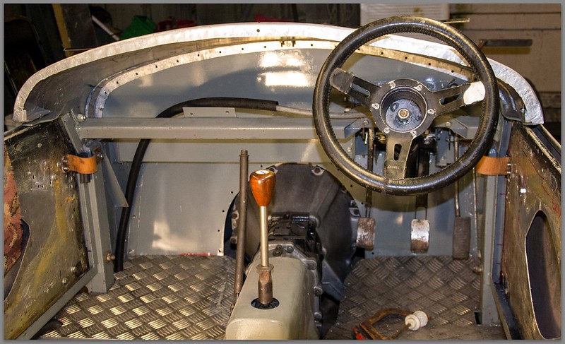
With this:

Not very pretty I know, yet! I am using a scrap bit of aluminium sheet to make a template for the dash and a scrap of MDF for the instruments, no way am I going to risk my newly acquired speedo and tacho during this phase of the construction. Once all the heavy work is complete I will fit the precious instruments.
I have settled for putting the instrument cluster in front of the steering wheel rather than in the centre of the console. I think the only other instrument I will have will be a very old wind up Smiths 7 day clock which came from a pre war car we owned , I know not which. My father had made a wooden table lamp and fitted the clock into it but I think this will be a more fitting place for it.
I may make a simple panel for the ignition and lights switch in the centre of the console, or I may place them to the right of the speedo, out of the way. Michael wants me to create a cubby hole with a door at the passenger side so he can put 'stuff' in it...
My next dilemma is whether to use aluminium or stainless for the face of the dashboard. Aluminium I have and it's much easier to work than stainless but I want to make a swirl pattern on it and I think it will tarnish very quickly around here, polishing the aluminium will soon remove the swirl pattern and I am not that fond of polishing stuff anyway. On the other hand I can get some stainless I am sure, it will not tarnish as quickly as the aluminium and should retain the swirl pattern pretty well, I will just have to take the hit on the workability and assert myself!
I will see what is available in the way of stainless and take it from there.
|
20th March 2015, 08:08
|
|
Senior Member
|
|
Join Date: Dec 2013
Location: Sunny Cumbria
Posts: 470
|
|
The blue line around the dials in the photo above marks the frame behind the dials which supports them and the PCB for the various warning lamps and the illumination of the dials. I have cut the frame down to suit having just the speedo and tachco instruments. I also need to cut the PCB down to suit, Fortunately most of the connections are from the plug pins remaining on the back of the PCB. However I will have to link some of the tracks and make one or two new connections to the PCB.
Having looked at the above picture I feel it might be better if I lowered the steering wheel a little to improve the view of the dials. I will try lowering the column this morning and see what it's like. The last photo above is pretty much a drivers eye view of the dials and although I can see all the relevant parts needed for driving, it would be nice to see the entire dials. That's one reason I fitted the larger 15" steering wheel, the previous black wheel was only 13" and only intended as a stopgap during the heavy part of the build so my 'good' wheel didn't get too damaged. With no power steering I think it will need a 15" steering wheel.
Last edited by 8 Valve Ed; 20th March 2015 at 08:10..
Reason: duplication
|
20th March 2015, 19:19
|
|
Senior Member
Enthusiast
|
|
Join Date: Sep 2004
Posts: 1,891
|
|
Quote:
Originally Posted by 8 Valve Ed
Well, I have started to fill this gap:
With this:
Not very pretty I know, yet! I am using a scrap bit of aluminium sheet to make a template for the dash and a scrap of MDF for the instruments, no way am I going to risk my newly acquired speedo and tacho during this phase of the construction. Once all the heavy work is complete I will fit the precious instruments.
I have settled for putting the instrument cluster in front of the steering wheel rather than in the centre of the console. I think the only other instrument I will have will be a very old wind up Smiths 7 day clock which came from a pre war car we owned , I know not which. My father had made a wooden table lamp and fitted the clock into it but I think this will be a more fitting place for it.
I may make a simple panel for the ignition and lights switch in the centre of the console, or I may place them to the right of the speedo, out of the way. Michael wants me to create a cubby hole with a door at the passenger side so he can put 'stuff' in it...
My next dilemma is whether to use aluminium or stainless for the face of the dashboard. Aluminium I have and it's much easier to work than stainless but I want to make a swirl pattern on it and I think it will tarnish very quickly around here, polishing the aluminium will soon remove the swirl pattern and I am not that fond of polishing stuff anyway. On the other hand I can get some stainless I am sure, it will not tarnish as quickly as the aluminium and should retain the swirl pattern pretty well, I will just have to take the hit on the workability and assert myself!
I will see what is available in the way of stainless and take it from there. |
When I investigated engine turned finish I was told alluminium, with the occaisonal coat of furniture polish, was the best solution. And considerably easier than stainless!
Cheers, Robin
|
20th March 2015, 21:07
|
|
Senior Member
|
|
Join Date: Dec 2013
Location: Sunny Cumbria
Posts: 470
|
|
Quote:
Originally Posted by MartinClan
When I investigated engine turned finish I was told alluminium, with the occaisonal coat of furniture polish, was the best solution. And considerably easier than stainless!
Cheers, Robin
|
That's interesting Robin... I have the perfect sheet of 1.5mm aluminium almost the exact size I need for the dash. It's years (probably 50!) since I last made those swirly marks, I used a felt bobbin and some coarse valve grinding paste. I don't mind the occasion coat of furniture polish...
You call the process engine turning? Not heard of that name. What's the current DIY method of producing them on aluminium?
I was proposing to use either some sand paper glued to a pad in the drill or some Scotchbrite glued to a pad in the drill or make a wooden stick, like a table leg about two inches round somehow held in the drill with coarse grinding paste applied to the end grain. I need to do some experiments... I seem to remember the effect faded as I worked across the sheet, as I got to the other side all I was doing was polishing it, in circles!
I have dropped the steering column slightly and it has made all the difference to the visibility of the dials. Although I have been very busy all day I don't seem to have DONE anything! I am working mainly on the dash area, cutting and welding little brackets for the dash and for the Kenlowe fan mountings which have been put off to often I have to address that little task. I haven't taken any photo's today, nothing really finished, just a lot of work done.
I have spent most of the day hobbling about because the soles of my feet are full of fine metal spikes. I just came back from Asda and my feet were in agony, I have put them in hot salty water and Michael has kindly pulled all the metal out of the skin on the soles of my feet. I have good boots but the metal grindings seem to work into my boots through the lace holes. I need a pair of spats!
Looking forward to a good day tomorrow. Maybe get a few more jobs ticked off.
Last edited by 8 Valve Ed; 21st March 2015 at 07:40..
Reason: Correcting preemptive text input, Grrrr
|
21st March 2015, 16:45
|
|
Senior Member
Enthusiast
|
|
Join Date: Sep 2004
Posts: 1,891
|
|
When experimenting I got fair results using a circle of scotchbrite on a stick. I used wd40 as a lubricant. If you have the patience small circles ~1" overlapped to look like quarters seems to look good. As usual there are shed loads of vidieos on you tube.
Cheers, Robin
|
|
Currently Active Users Viewing This Thread: 2 (0 members and 2 guests)
|
|
|
 Posting Rules
|
You may not post new threads
You may not post replies
You may not post attachments
You may not edit your posts
HTML code is Off
|
|
|
All times are GMT +0. The time now is 03:57.
|


 Linear Mode

