|
|
| Sammio Builds and discussions Sammio bodied car builds and specials |

30th March 2014, 08:28
|
 |
Senior Member
|
|
Join Date: Feb 2012
Location: Wembley, London
Posts: 5,056
|
|

After an epic gardening session yesterday, I was also able to get a little bit done outside before the sun went down...
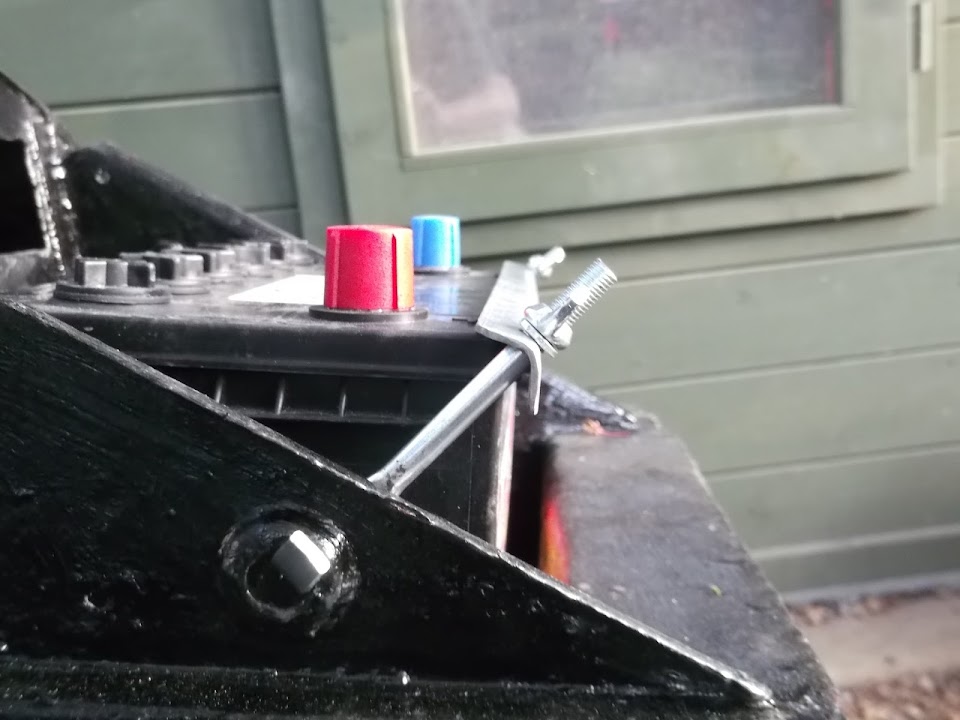
Battery:
I test fitted my new battery, but the new retaining bracket did not want to line up / work properly.
( Admittedly, the battery sits much lower than standard in my home made battery box. )
Thankfully I found something suitable in the box of bits that came with my donor car.

Although I still had the issue with the length of the bolts.

So out came the angle grinder to trim both the width of the bracket & length of the bolts.
Then I added the foam strip that came with the new bracket.

So now it all looks a lot better.

- - - - - - - - - - - - - - -
Battery Cut Off Switch:
I had also bought two new battery leads:
- One for the battery terminal to the cut off switch.
- The other from the cut off switch to the bulkhead earth.

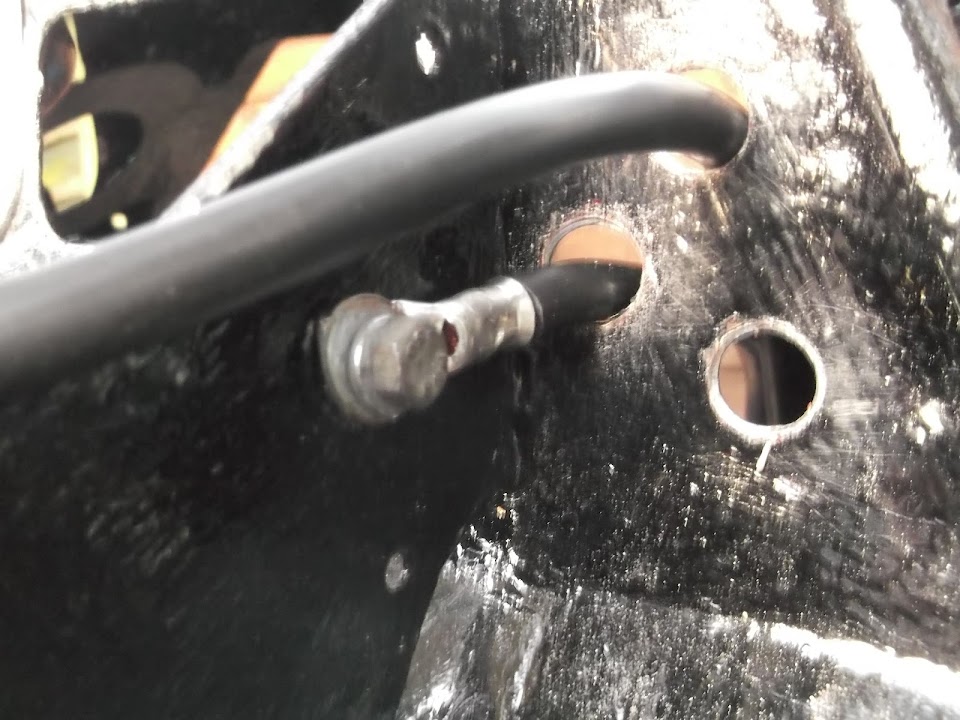
It was only when I came to fit them that I noticed another school boy error.

I'd measured the "ring" end of the original battery cable (bottom right) and made sure the new ones matched.
However, what I should have done is measure the size of the cut off switch bolts, as they are bigger. 
My temporary fix was to open up the "ring" like so.

The next step was to drill two holes in the bulkhead so the leads could be connected to the switch.

Unfortunately, " Amateur Night" continued as I managed to make a hash of this simple task too. 
I've actually ended up with three holes to avoid a severe bend in one of the leads.

The only good news is that I have had plenty of practise welding up holes in this bulkhead.
So this is the route the battery cable will take going into the bulkhead.
( Some new rubber grommets for the holes have been ordered. )

Then the return cable will come back out here and connect to the original Spitfire earthing point.
( Other cables will also be attached to this point. )
At some point I will a few holes in the bulkhead for some pop rivets to hold some zip tie mounts.
Then I can use the zip ties to keep the two cables apart and tuck them neatly out of the way.
But that's all for this update, so until next time, take care, Paul. 

|
31st March 2014, 14:03
|
 |
Senior Member
|
|
Join Date: May 2011
Location: Somerset
Posts: 1,671
|
|
Starting to come together really nicely matey!
At one of the shows the other year i picked up a "big pack-o-gromets" some blanked off, some not. I rate it as one of my best under a fiver purchases as you don't realise how useful they are until you've got them. |
1st April 2014, 18:22
|
|
Senior Member
|
|
Join Date: Feb 2012
Location: Wembley, London
Posts: 5,056
|
|
Dave - Cheers, I know it has taken me a long time to get this far, but the bulkhead does give me hope.
You're right about things like grommets, as all the little "bits & pieces" required to build the car soon add up!
- - - - - - - - - - - - - - - - - - - - - - - - - - - - - - -
Here is round up of what I've managed to squeeze in over the last few days...
Wiring Loom - Part 2:
I'd found the two "power" wires I needed for my side repeaters running from the indicator switch through the wires behind the dash.

I plan to fit the side repeaters to the main bodywork, rather than the flip up bonnet as seen here on tlrtone's build.
( Don't get me wrong, they look good there, but it seems like a long wiring route to me. )
Rather than cut these power wires, I simply "skinned" a small section of insulation off them.
Then I could wrap the ends of two small lengths of "spare" wires in matching colours to each wire.

I just needed to add some solder before wrapping the "T" junctions
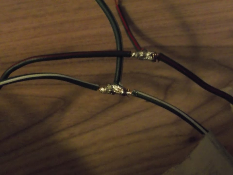

With the "power" wires for the side repeaters wiring taken care of, next up was providing then with an earth feed...
- - - - - - - - - - - - - - -
There was a "spare" earth wire running through the loom behind the centre of the dash, originally used for the old heater.

But I wanted to add three extra lengths of wire to it at this point.
- Two to correspond with the left & right side repeater wires I'd just set up above.
- Plus one more to connect with the earthing point I'm using for the new micro heater.
I figured trying to wrap lots of wire together would just make a big mess.
So instead I used 5 of the small ring/eye connectors that came with my crimping tool.

Together with my new pop riveting skills, I could now make a five way connection like so.
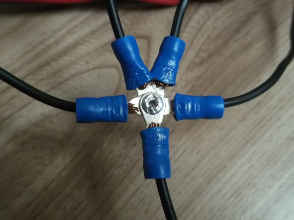

The wiring behind the centre section of the dash now looked like this.

With the new earth wire and the previously connected green fan speed switch wire coming straight down.
But before I could finish wrapping up this section of the loom there was another job to finish first...
- - - - - - - - - - - - - - -
When I first stripped my donor, there were two "random" wires in the engine bay not connected to anything.
Later on, when I started thinning out the wiring loom, I discovered both these wires ran to the oil warning light.
But after looking at more wiring diagrams, it turns out one of these wires is actually for a PDWA switch.
( Pressure Differential Warning Actuator )
This is linked to the fact I am running the dual (tandem) brake system from my late model 1500 donor.
The "plug" end of the cable looked like it had seen better days & may never have been used at all.

Also the PDWA wiring does not appear on any of the UK wiring diagrams I have, only the USA ones.
Plus the corresponding warning light on the speedo is simply marked "Oil" & makes no reference to brakes.

So I have decided to remove the PDWA wiring altogether to keep the wiring I do want much simpler.
The only problem with this "master plan" was one end of the wire was in the engine bay section of the loom.

So I unwrapped this a section at a time, adding tape back to hold the cable routes in their original positions after I'd removed the wire.

Eventually, I had all the surplus wires I wanted to remove in one place.

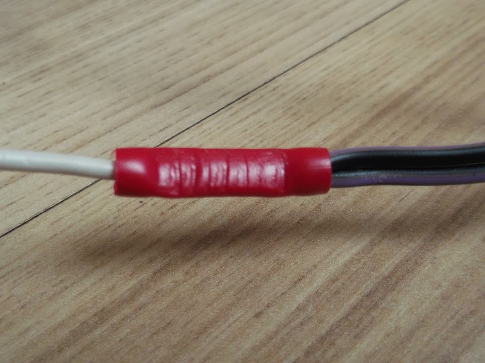
Just one of these two black/purple cables needed to be connected to a single white wire in the loom.

But just to be on the safe side I joined them both to the white wire.
( It has taken me a while to start using these crimp connectors that came with my pliers, but they are handy. )
This was the pile of spaghetti for the area behind the steering wheel before I removed the PDWA wires.

But before I started to tackle the rest of this mess, I went back to the centre dashboard wiring...
|
1st April 2014, 18:25
|
|
Senior Member
|
|
Join Date: Feb 2012
Location: Wembley, London
Posts: 5,056
|
|
Wiring Loom - Part 3:
With the PDWA wires removed, and the other wires running through here double checked, the centre dash section was now done.
So I wrapped it all up and it was nice to see one small part of the much bigger job complete. 


In addition to the side repeater "spurs" pointing upwards in this section, there is also the ignition key wiring.
- - - - - - - - - - - - - - -
I'd found a broken wire from one of the previous owners mods when I dismantled my donor.

This had linked the rev. counter earth to the high beam warning light earth.
However, this earth wire also had been "flattened" at some point.

So I decided to sort this all out properly while I was knee deep in wires anyway.
I wanted to keep the three speedo warning lights on a separate cable route anyway.
So I added the high beam warning light earth wire to another earth wire in the main loom.

As I'd already sorted out the oil warning light, I could now wrap the wires for these three bulbs.

Now I just needed to sort out the earth lead for the rev counter, but there was another problem...
- - - - - - - - - - - - - - -
I have been working with my notes and old photos, but the earth leads & dial bulb marked for the speedo just didn't look right.
In fact, I couldn't find a nice way to route most of the wiring while keeping the dash layout the way the previous owner had it.

After a lot of beard scratching I had convinced myself that the dials must have been fitted the wrong way round.
Sure enough, a quick search of Google images gave me a standard layout with the speedo on the left & rev counter on the right!

Once I'd calmed down a bit, I simply re-arranged the dials on the floor and instantly the wiring lengths/routes made more sense.

So it turns out that the oil pressure gauge bulb (far right) is actually an extension of the rev. counter bulb, not the speedo one.
Whilst it was good to know I can trust my instincts (occasionally!), it had been a frustrating waste of time.
The rev counter earth wire was set up just like the high beam warning light (1 earth wire becomes 2).
Any with that final fix for this section of wires in place I could finally see the rough layout I needed.
Note: This is not how they fit, just the separate routes I am going to have.

Then it was time to wrap up the vast majority of the wires behind the steering wheel.

This section also includes the wires that connect to the brake light switch behind the brake pedal.
I've left wires for the flasher unit and the hazard flasher unit unwrapped for now, until I can check where they are fitted relative to everything else.

- - - - - - - - - - - - - - -
When I first thinned the loom out, I cut one wire in error from the connection block that goes to the indicator/horn switch.
Rather than attempt to fix the mess I'd made of the original connecting block, I simply added an extra connection.
However, for this to work, I had to wrap a "bend" in the rest of the wires to create some slack.
( As my previous butchery had left the wires too short. )

Whilst this is clearly not as tidy as the original set up, it will work well enough for me.
|
1st April 2014, 18:26
|
|
Senior Member
|
|
Join Date: Feb 2012
Location: Wembley, London
Posts: 5,056
|
|
Wiring Loom - Part 4:
I continued working my way along the loom until I got to the section of wires near the fuses.
This included the second (of two) mistakes that I'd made when thinning out the loom the first time.
I'd cut out the green & black wire to the left with the masking tape on it in error, but is was now too short to rejoin at the fuse box.

In addition, there was a "stray" earth lead that wasn't going to fold up/tuck away neatly either.

So I used two more of my red connecting tubes to tidy up the wires & their routes.
- The green & black wire now joins one of the green wires a bit earlier than at the fuse box itself.
- The earth wire is now a single lead to "earth", with the rest of the wire the right size to tuck in nicely.

Which meant another section of the loom could be wrapped up.

Note:
The collection of wires heading off to the bottom of this photo are for the rear lighting.
But I still need to work out the route they will take from the bulkhead through the rest of the car.
- - - - - - - - - - - - - - -
The next batch of wiring work could only start when the new connecting blocks I'd ordered arrived.
( 4 x 4 way connectors + 5 x 2 way connectors. )
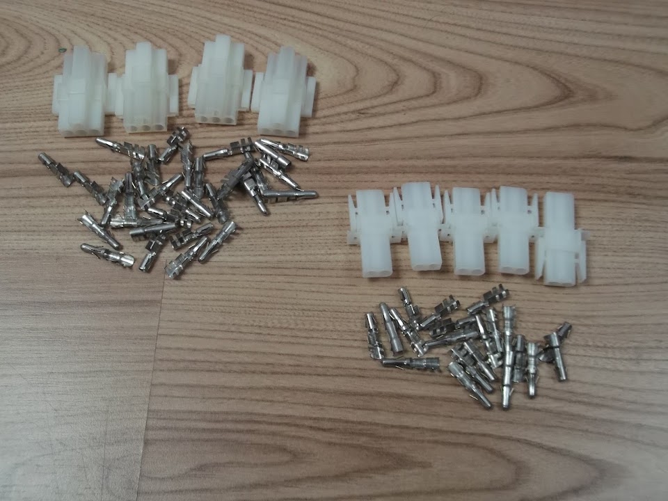
I will be using these to join the old loom to the wiring for the front & rear lighting + side repeaters.
However, there was only so much I could do indoors without the full loom being laid out across the chassis / bodywork.
So I started by simply fitting one side/half of a 4 pin block to the headlight wiring.
( It is amazing just how long ago I started playing with the wires for these things. )
There were three original wires, plus one new wire I'd added for the built in side light.

These wires were then cut to size & fixed into the pins.

Note:
The cable clamps were too "flat" at this point & needed to be squashed a bit rounder to fit inside the plastic block.

But once I'd got the hang of it, it was simply a matter of taking my time and repeating the process.
Eventually I had completed the other headlight cable and the wiring for the two front indicators.

Obviously the indicators only need a two pin connector.

The other halves of all these blocks will be fitted to the main loom, when I can finalise the wiring route/length required.
Note:
Just before I wired up the second headlight, it dawned on me it would be handy if each block was wired the same way.
So luckily either headlight will plug into either side of the loom, provided I remember to do the same with the loom block.
- - - - - - - - - - - - - - -
In addition to working on the indicator wiring, I've also been thinking about their location on the car.
Micky1Mo posted this photo of his Navigator/Spitfire hybrid the other day.

KISS principles would suggest doing something very similar on my own build to save both time & effort.
Mind you, it will be a while before I need to finalise this plan, so back to the wiring loom...
- - - - - - - - - - - - - - -
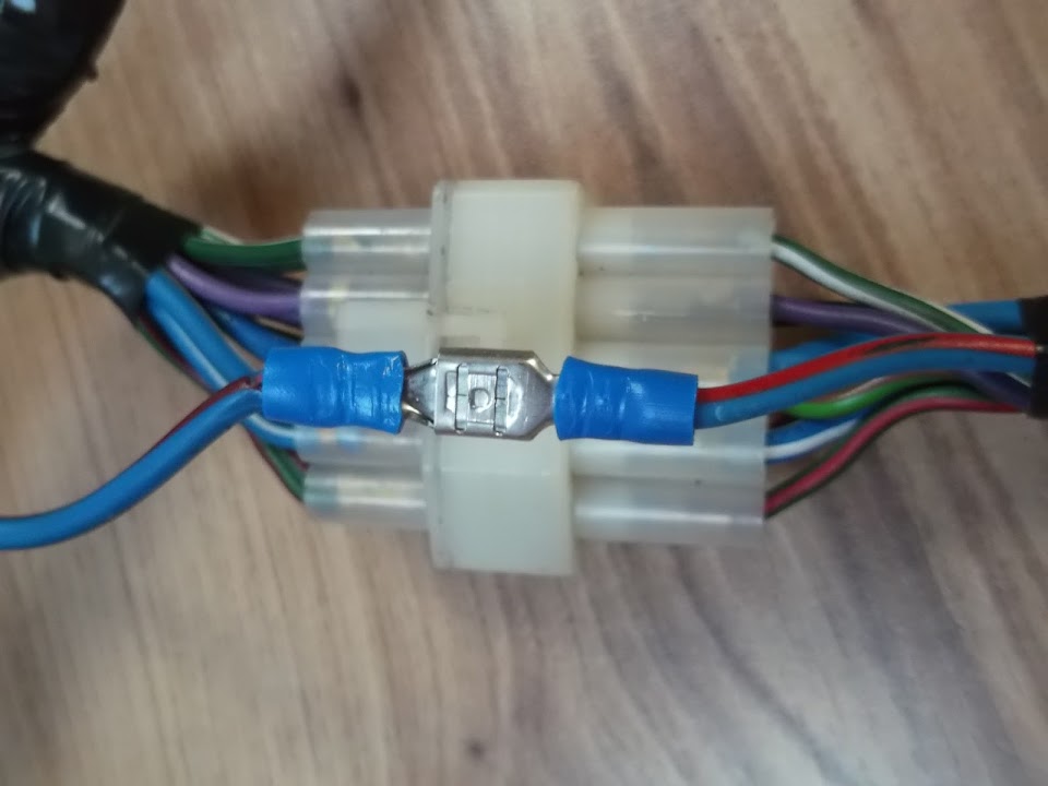
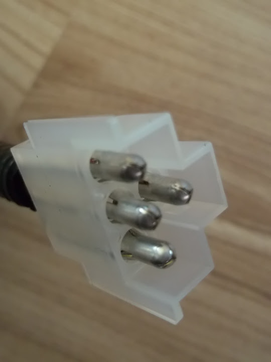
My final bit of work on the loom for now was to add two small blocks to the side repeater feeds.

I have set the connectors up so that the 'female' ends will be on the loom & the 'male' end on the lights, etc.

As before, the other half of these blocks will be added when the wires to the lights themselves are cut to length.
I must say I am really impressed with how easy these connectors are to use and how professional they look.
- - - - - - - - - - - - - - -
Finally, I'm also making good progress on "non car" stuff, but need to concentrate solely on that again for a while.
So until next time, take care, Paul.
|
1st April 2014, 20:29
|
|
Senior Member
|
|
Join Date: May 2013
Posts: 2,161
|
|
That lot looks really good Paul, I'll know who to ask when I need to do mine!
My wiring looks a real mess at present!
|
3rd April 2014, 08:21
|
|
Senior Member
|
|
Join Date: Feb 2012
Location: Wembley, London
Posts: 5,056
|
|
Scottie - Thanks.
I am actually enjoying the wiring and now have a much better idea how it all joins up.
Also, I really like the look of those connecting blocks from AES (Auto Electrical Supplies).
- - - - - - - - - - - - - - - - - - - - - - - - - - - - - - -
I know I am supposed to be doing other things, but I loved the photos in yesterday's "Ribble News".
Car #274 is a Pilot/Spyder body with a Navigator/Cordite bonnet fitted.
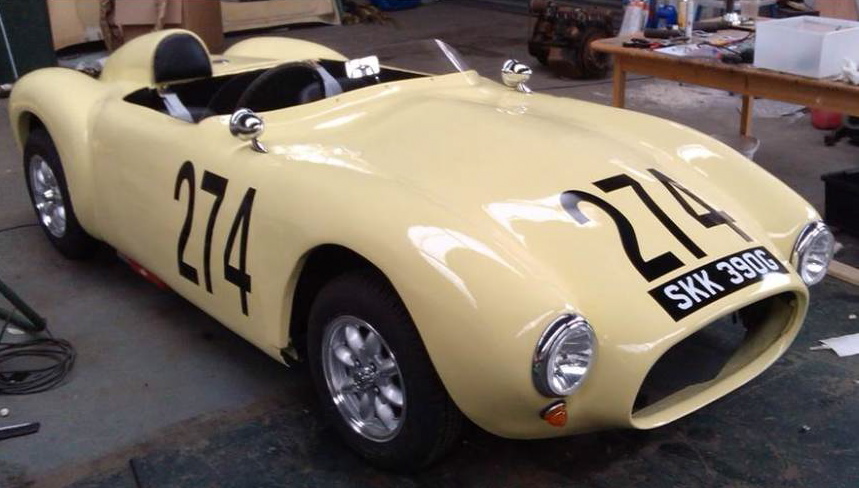
I have similar alloy wheels, the same type of chrome bullet side mirrors, similar lighting, etc.
So this actually gives a pretty good impression of what I am trying to achieve.
Although, I prefer to use racing roundels if I decide to put #7 (Cordite kit number) on my car.
The other thing I like about this is the way the front indicator still looks good at a downward angle.
I'd rejected this idea when I tested it with my, much larger, Land Rover rear indicator lens a long time ago.

But I now have the same classic mini front indicators to use and so I will copy this idea.
Yes, I know, it was only a few days ago that I said I would copy Micky1Mo's indicators in the grille idea.
Perhaps I should drill some holes in the bonnet straightaway before any more photos are published! 
Finally, I had also got to the bottom of the retaining the headlight rim (see Mac's build).
The 1500 used a different headlight fitting altogether, so I'd order two second hand ones.
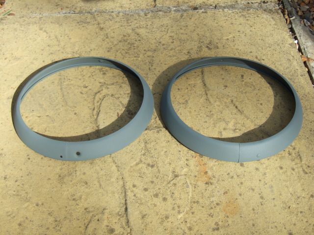
But one came with a hole for a fixing screw and one didn't.
Anyway, I had brought a complete headlight assembly indoors when working on the wiring loom.
But a quick check with Rimmer Brothers showed I was missing the retaining clip in this photo.
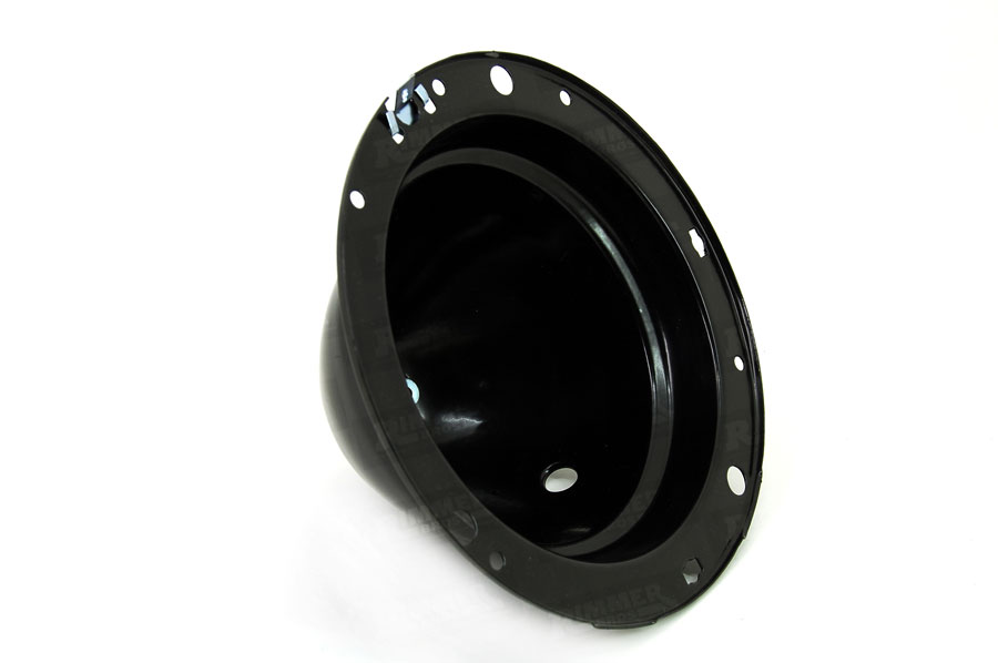
So I need to see if I set up something that will work with the box of clips I have.
Plus I will need to drill a hole in the headlight rim that currently doesn't have one.
Anyway, that all for now, as I really need to go.
Cheers, Paul.
|
3rd April 2014, 13:14
|
|
Senior Member
|
|
Join Date: May 2013
Posts: 2,161
|
|
Indicators
[IMG]  [/IMG] |
4th April 2014, 07:59
|
|
Senior Member
|
|
Join Date: Feb 2012
Location: Wembley, London
Posts: 5,056
|
|
Scottie - Please don't show me more front indicator options, as you know what I'm like.
( See below for confirmation. )
Mac - Thanks for the link, I've put an order in for a couple of those clips.
- - - - - - - - - - - - - - - - - - - - - - - - - - - - - - -
KISS and just stick to the plan...
Perhaps it might be better if I don't follow other builds on here, as I appear to be easily lead.
But playing with the wiring loom was bound to get me thinking about my lights wasn't it?
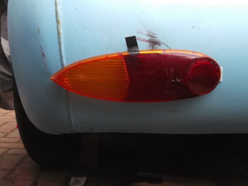
This was always my plan for the back of my car...

Note: Obviously, everything would be nicely spaced apart and aligned horizontally.
Then I saw what Micky1Mo & HouseMartin had done at the back of their G-46s...


Part of me was convinced that fitting a single rear light cluster would be less effort.
So, before I knew it, I'd bought a cheap pair of Austin units on Ebay that looked like they might do the job.

These units were actually a lot bigger in real life, than they looked in the photo or I expected.
Either that, or the back end of a G-46 really is HUGE!
So there wasn't really an idea position to fit them on my Cordite bodywork...
Option #1:


Option #2:


I think it would be possible to make these fit with a bit / a lot of work.
But quite frankly, I've already got so much work to do as it is, so these lights will not be used.
Instead, they will eventually be going back on ebay, unless anyone on here wants them.
And I will stick with the original rear lighting that I have, although I might rearrange the layout a bit...


Decisions, decisions, but thankfully I can worry about that another day.
Take care, Paul.
Last edited by Paul L; 4th April 2014 at 08:17..
Reason: Missed off a reply when copying & pasting across!
|
4th April 2014, 08:18
|
 |
Senior Member
|
|
Join Date: Jul 2011
Posts: 5,328
|
|
Paul, have you tried the Austin units placed horizontally instead of vertically? Could look pretty neat...
|
4th April 2014, 11:39
|
|
Senior Member
|
|
Join Date: Jun 2011
Location: birchington, kent
Posts: 1,769
|
|
Paul, i'm going to 'french' mine into the bodywork.
|
4th April 2014, 12:48
|
|
Senior Member
|
|
Join Date: Feb 2012
Location: Wembley, London
Posts: 5,056
|
|
Mr T - Well I have now.
Test fitting them horizontally certainly gives a much closer (easier) fit.

Although they are so big I'm not sure that there is much room left for the number plate.
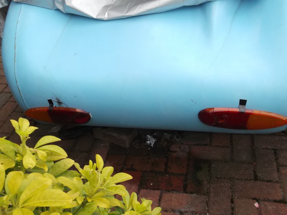
Sorry I can't get any better photos, but the last one was taken with me standing in my neighbour's front garden.
The close up photos involve me holding the camera in the bushes that separate each of our "semis" & hoping for the best.
Gary - I did like the way Gaz had the rear lights "Frenched" on G-46 #1.
But, for me, that definitely falls into the lots of extra bodywork category.
With a big of luck, I hope to test fix the bulkhead to the chassis next week.
And that will be a major step in the right direction for this build.
Cheers, Paul.
|
4th April 2014, 13:58
|
|
Senior Member
|
|
Join Date: Jun 2011
Location: birchington, kent
Posts: 1,769
|
|
These look silly on their sides...
|
4th April 2014, 14:18
|
|
Senior Member
|
|
Join Date: Jul 2011
Posts: 5,328
|
|
Quote:
Originally Posted by garyh

These look silly on their sides...
|
Yes, they are a bit on the big side.
They might work a bit better turned round so the reflectors are on the outside, or you might just want to relist them on ebay at twice what you paid... |
4th April 2014, 14:26
|
|
Member
|
|
Join Date: Apr 2012
Posts: 45
|
|
Paul, interested in taking these off your hands if you don't use them. I'll PM you
Craig
|
5th April 2014, 22:53
|
|
Senior Member
|
|
Join Date: Feb 2012
Location: Wembley, London
Posts: 5,056
|
|
Gary & Mr T - No worries, I figured it was worth at least trying the lights.
Craig - The Austin lights will be wrapped up and on there way to you soon.
- - - - - - - - - - - - - - - - - - - - - - - - - - - - - - -
A long day - Part 1:
By swapping my planned workload around a bit, I could actually play outside earlier today.
Based on the weather forecast, I will be doing my "non car" stuff when it is raining outside over the next few days.
However, first thing in the morning I still had to do some gardening.
I finished sorting out the climbers on one side of our patio.
They looked like this a few weeks ago when I was treating the garden furniture.

And now they look like this...

I will have to replace all the trellis at some point, but today's make do & mend repairs will last at least another year.
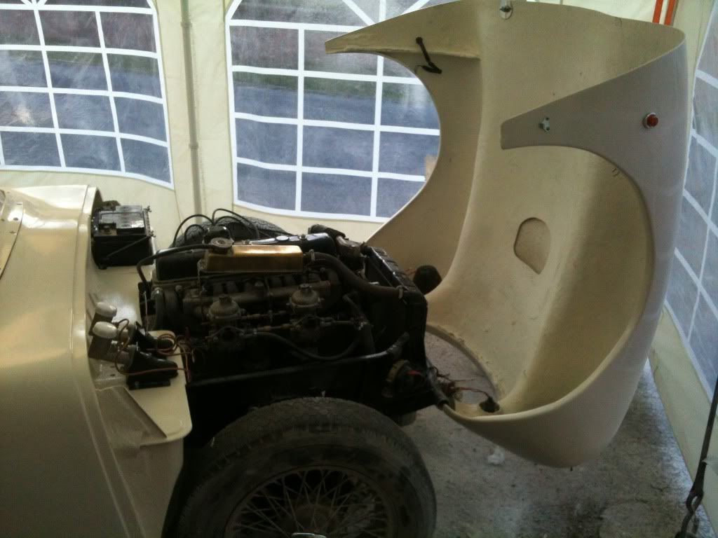
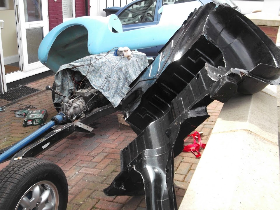
With that job ticked off, I removed the covers from the "car" on my front drive for the first time since October.
I guess I'd forgotten just how much rain we've had since then, as this is the sight that greeted me.

Although, given the paw prints on the floors, I have a bad feeling this may not be just water damage! 


These floors need some final adjustments anyway, so I'll worry about sorting this mess out later on.
Instead, I simply got on with making some adjustments to the bodywork.
I wanted to remove a bit of the door cut out, so the metal framework couldn't touch it.

After lifting the body off the frame & a quick session with the jigsaw, I'd removed a section from both sides.


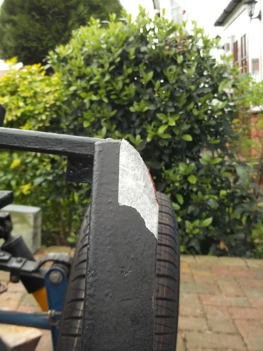
I had also noticed that if the body went much lower, it would foul at this edge of the rear frame.

So I rounded off the corners on both sides with my angle grinder.
Then my wife helped me to carry the bulkhead through the house to the front drive.

My wife deserves a medal for the amount of lifting she did today.
( Bulkhead, rear wheel arches, rear frame & body shell. )
I can just about move most things, but it is seriously hard work, so she really helped me out today.
First job on the bulkhead was removing the box section cross brace.

Given all the repair work I've done, I'm really pleased with how solid it still feels without the brace.
Obviously I will be tidying up the paint work at some point.
After lifting the bulkhead into place it looked like this.


The good news is that my brake master cylinder tucks into the recess I made for it.

The bad news is that the top still seems high to me, but I am still a long way from worrying about that.

Continued...
|
5th April 2014, 22:55
|
|
Senior Member
|
|
Join Date: Feb 2012
Location: Wembley, London
Posts: 5,056
|
|
A long day - Part 2:
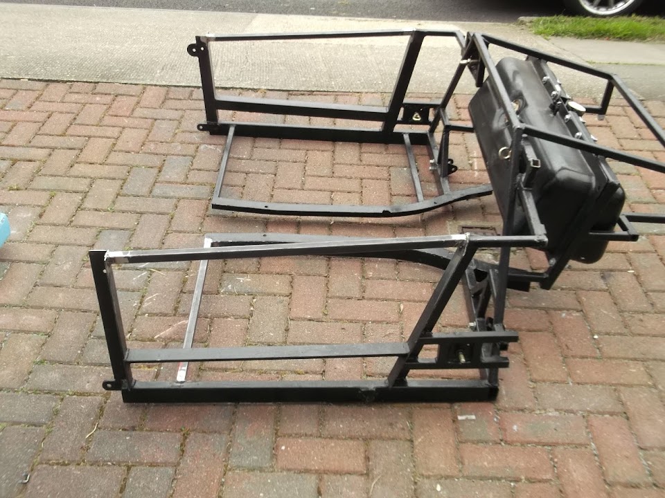
The first big job was to sort out the rear frame work.
But before I get to that, the following photos give you some idea of the madness that is building a car on your drive!

The frame had been supplied with a "wonky" cross rail on the passenger side.
( Note: From the old Sammio, not the new Ribble, days. )

Note: This is how the driver's side looks.

Initially, I had trimmed the lowered floor pan on this side to work around this problem.
Because at that stage, the thought of making a change to the "factory" frame slightly scared me.
But there has been a lot of metal work under the bridge since then!
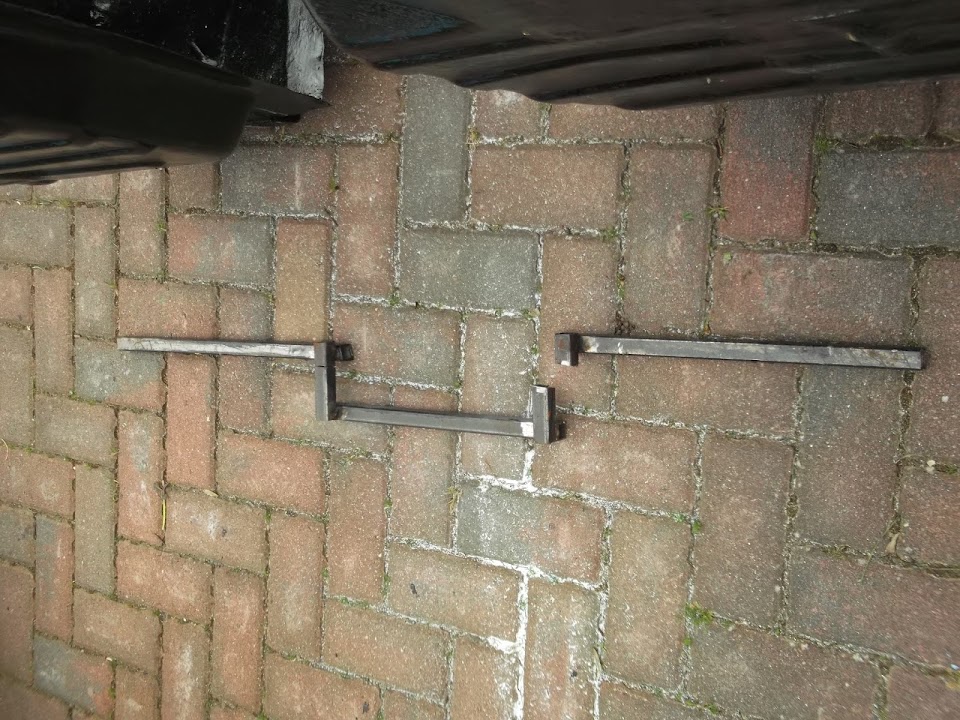
Now, I simply marked up the changes I wanted to make and got on with it.
So out with the old...

And in with the new...


Now that's much better...
With this frame rail in a new position, I could re-fit the lowered floor pan.
But first I needed to trim off some of the excess metal from the front edge.


There is still a bit of fine tuning to do with this edge once the bulkhead is bolted down.
Plus the floor will be 'glassed to the bulkhead when I get to that stage.
The really good news is that the "straight" rail allows the floor to move forward a bit.
Compare where I'd marked the floor for cutting, with where the seat belt hole is now.

Due to the slope at the back of my seats, the old passenger floor / seat position was poor.
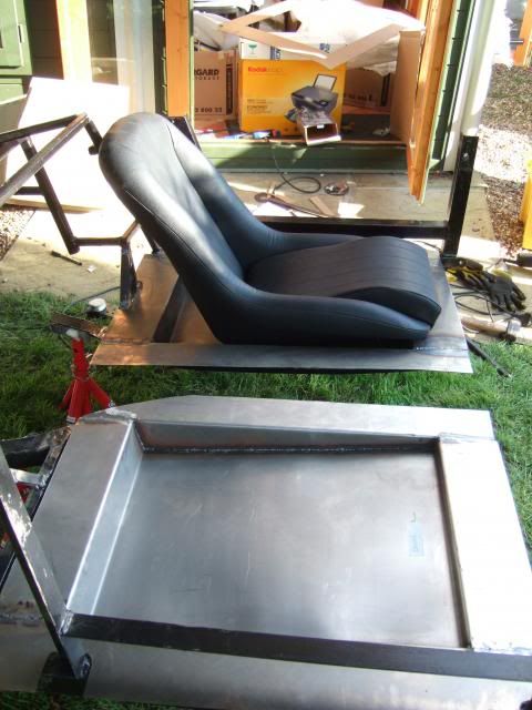
Because it meant the front of the seat had to hang over the front lip.
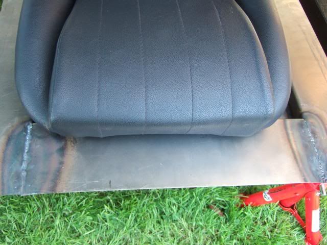
I didn't get a chance to test a seat in the new position, but that should have sorted it out.
Having dragged some of my tools and the welder from the bottom of the garden I wanted to make good use of them.
So I decided to weld in some box section across the door opening in the framework.
But before I started on that I needed to take some more out of the door openings in the bodywork.


Otherwise the body would not sit back on the modified frame work.
Note:
All of this door opening section will be removed when I come to seal up the doors.
But I wanted to fix the outer door skins in place first before I completely removed it.
After another blast with the jigsaw.

Continued...
|
5th April 2014, 22:59
|
|
Senior Member
|
|
Join Date: Feb 2012
Location: Wembley, London
Posts: 5,056
|
|
A long day - Part 3:
Then I cut two lengths of box section (obviously the two openings are different sizes ).

Then welded them in.
Frame back on the chassis.

Then bodywork back on the frame.

Note:
Until I cut the bodywork to fit around the bulkhead, it will still point upwards at the front.
Whilst the body work does now clear the door rail, there will be a limit on how far this can be lowered.
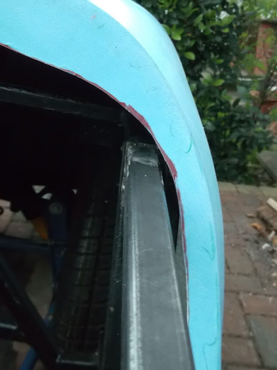
Mind you, there is so much bodywork to do, I'm trying not to think about it.
Although I did find myself looking at how much I might need to widen the cockpit to have plenty of room for my seats.

Still on the subject of bodywork, I need to bridge a gap of around 9 cms to cover the Spitfire bulkhead & dash.

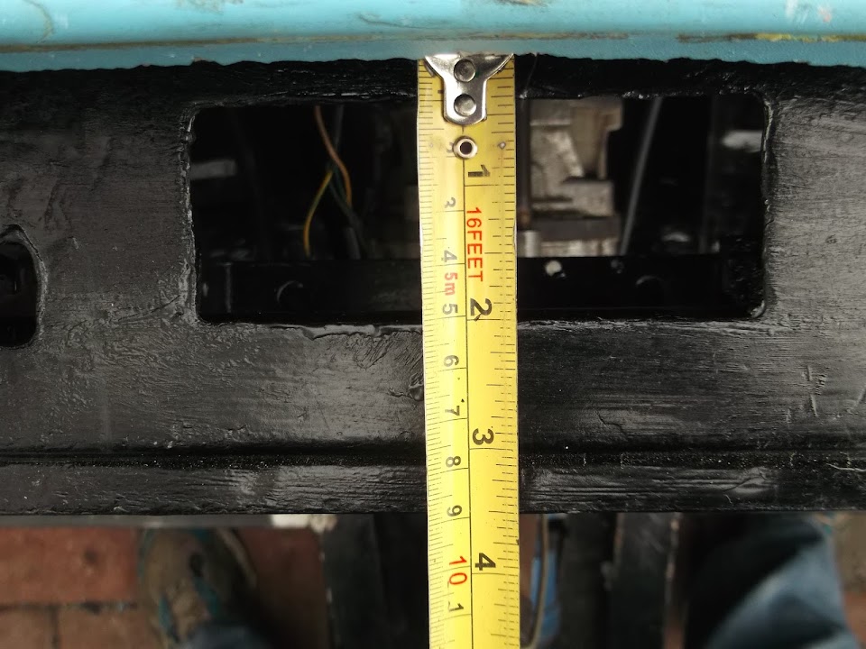
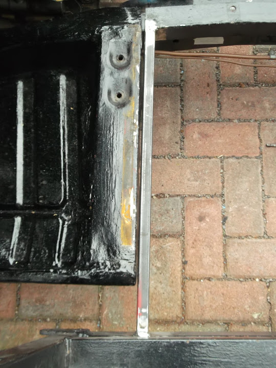
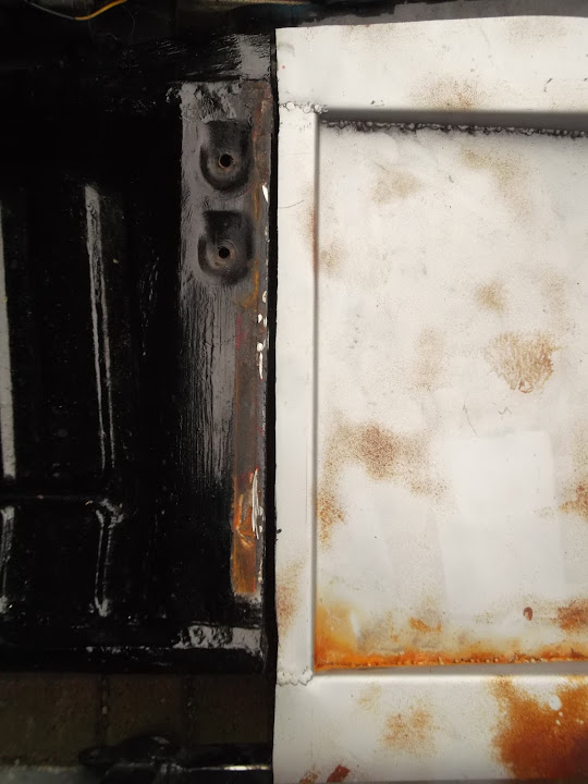
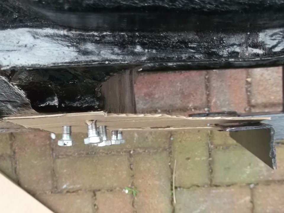
I just had time to start mocking up possible options for the "join" between bulkhead & rear frame.
I clamped the frame to the chassis to make sure things were in the right position.
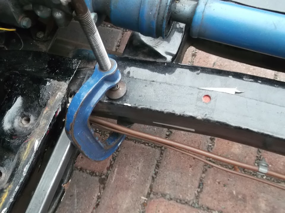
Then it was back to the cardboard again.

I'm not sure about design of the top bracket, so I will come back to this.
Due to the angles involved, the top bracket would be on the "inside" & the bottom bracket would be on the "outside" of the frame.
At this point I had to tidy up and pack everything away for the next few days.
I
've left the wheel arches off completely for now as they are just making the other jobs harder at the moment.
Finally, the new lugs for the ends of the earth leads attaching to the battery cut off switch arrived.

So I will need to remove the ends that were too small and fit these at some point.
The headlight rim retaining clips also arrived.

I am now completely knackered and in desperate need of some sleep, but it was a very productive day.
Take care & good night, Paul.
|
6th April 2014, 00:53
|
|
Senior Member
|
|
Join Date: Jul 2011
Posts: 490
|
|
Fab progress Paul. There are any number of processes you have mastered that seem very intimidating to someone like me that has, as yet, not had the time (nerve) to make that first decision / cut /weld / re wire / solder - great inspiration.
(Hope you clear any DIY chores over Easter to allow you time on your project build (and to post the results!)
|
|
Currently Active Users Viewing This Thread: 3 (0 members and 3 guests)
|
|
|
 Posting Rules
|
You may not post new threads
You may not post replies
You may not post attachments
You may not edit your posts
HTML code is Off
|
|
|
All times are GMT +0. The time now is 10:40.
|


 Linear Mode

