Oxford - Looking forward to seeing your approach in action.

- - - - - - - - - - - - - - - - - - - - - - - - - - - - - - -
Winter Time:
The clocks going back mark the start of my 4th Winter on this project.

However, looking back over the last few Winters, the good news is that, despite the weather, I still manage to make process.
So with a few hours available to spend on the car today, it was time to pull on my woolly hat and get on with it.
- - - - - - - - - - - - - - - - - - - - - - - - - - - - - - -
My wife helped me lift off the body shell, for what should be <
touch wood> the last time.

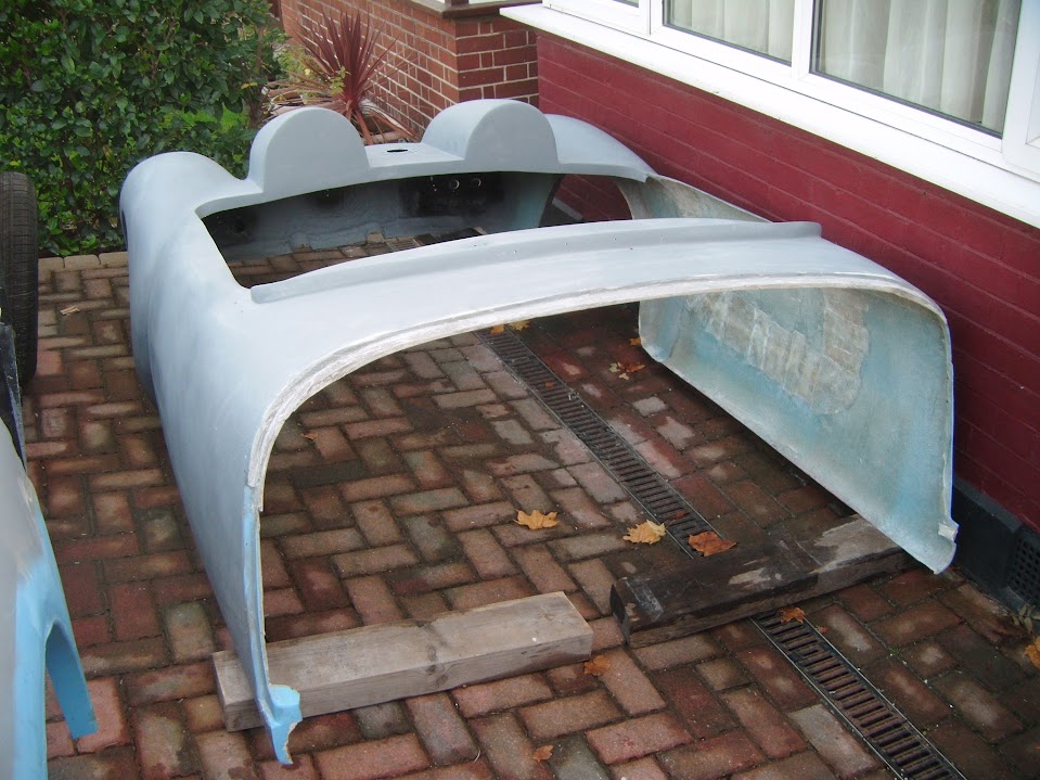
This will allow me to make the final adjustments required to both the body shell and the
Moon Rover.
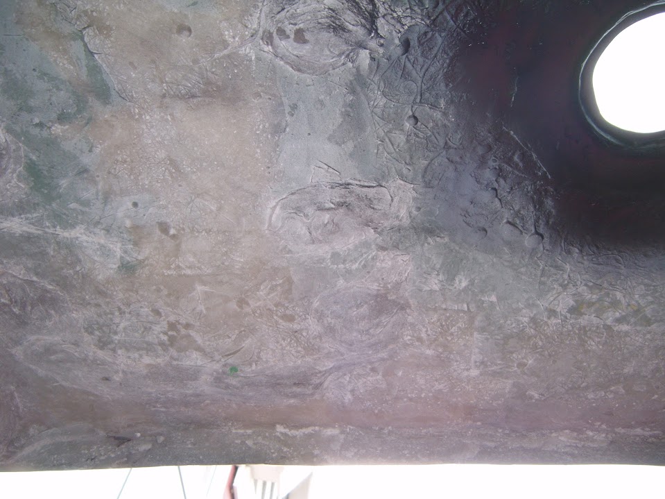
You may recall that I painted the area that extends beyond the bulkhead over the dash board.

Unfortunately, I forgot that there is a similar "over hang" at the front of the bulkhead too.
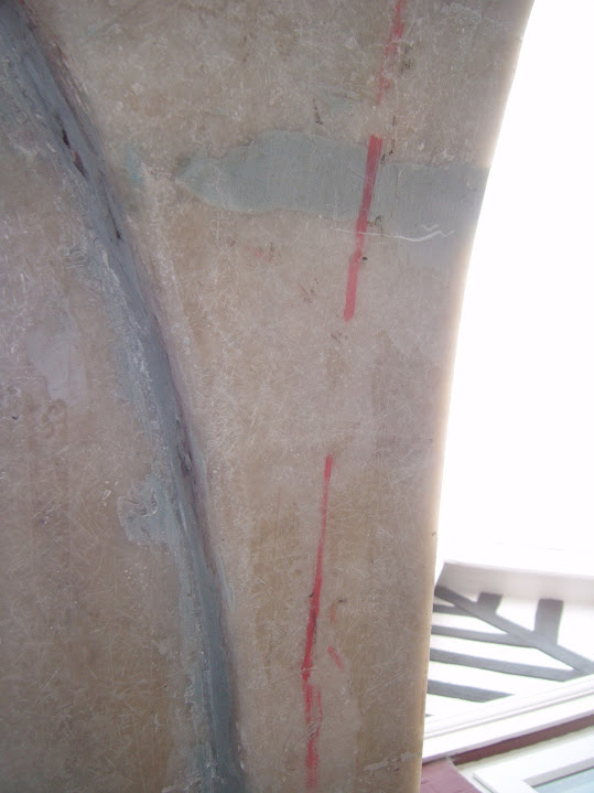
So I need to paint the area to the right of the red line in the photo above.
- - - - - - - - - - - - - - - - - - - - - - - - - - - - - - -
With the body shell out of the way, I was able to fine tune my "alignment tool", after adjusting one of the tail pipes.
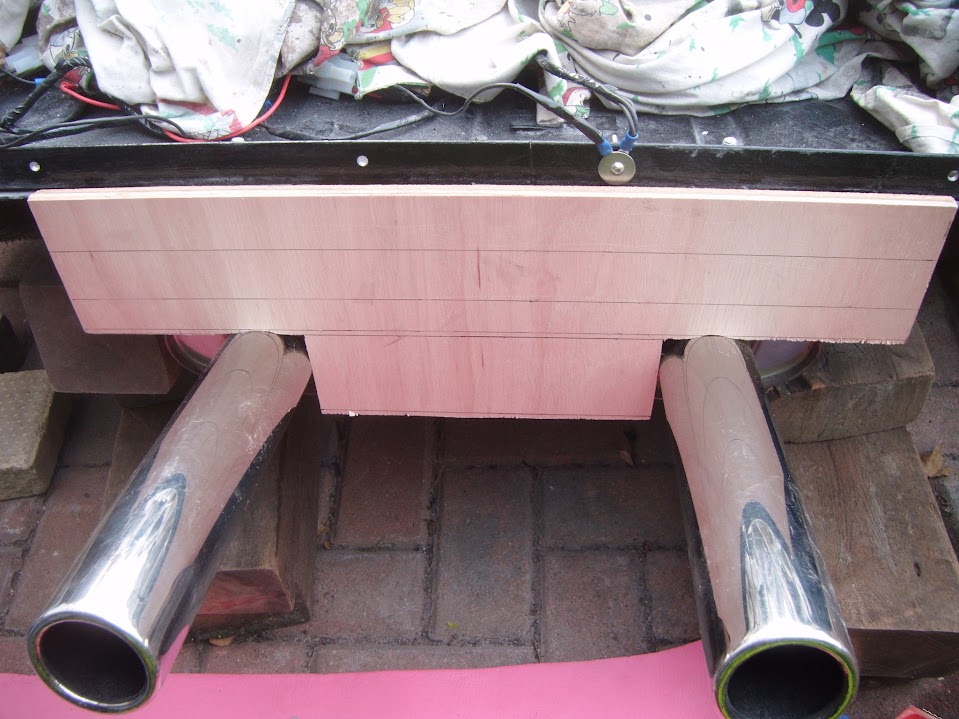
The bottom line is there no real datum point to work with, so the boot floor support bracket is now my reference point.
- - - - - - - - - - - - - - - - - - - - - - - - - - - - - - -
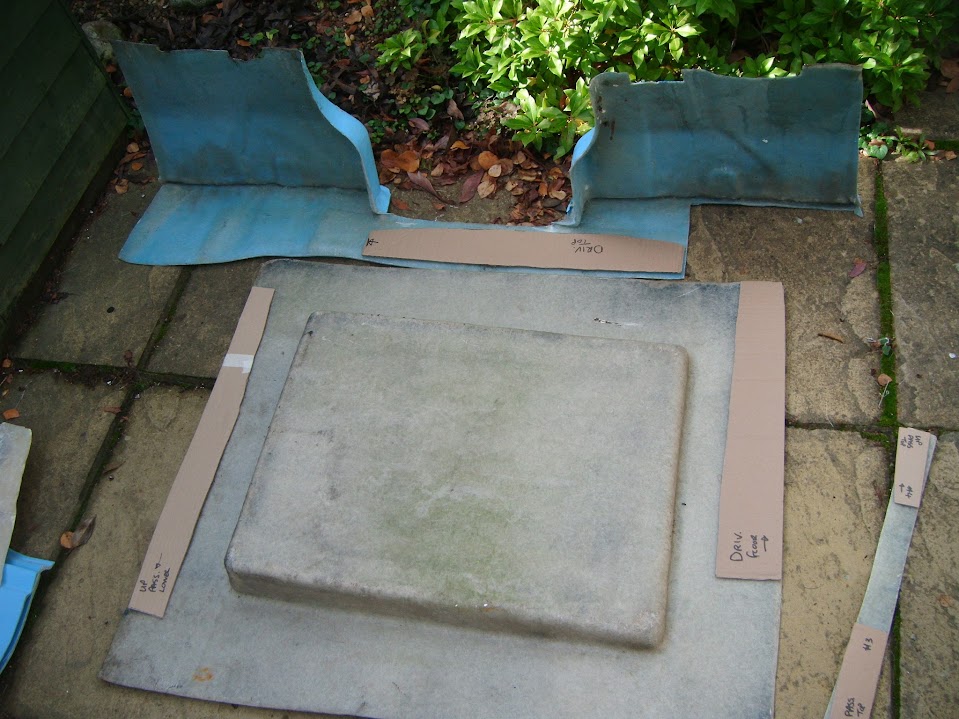
Thankfully, I remembered I was planning to recycle the main sections of the fibreglass floors into engine bay deflectors.
So I cut out the "bridging" sections I need for the sides of the body shell from other bits of 'left over' fibreglass.


- - - - - - - - - - - - - - - - - - - - - - - - - - - - - - -
I'd added a section of metal across the internal framework to help me brace the body shell between the humps.

But one thing that was always in the back of my mind was that the body shell did not cover the length of this support.
The following photos are taken from underneath the body shell, so they are not great.
However, you can still seen that on the passenger side, the extra hump was added on top of the body shell in this area.
Whereas, on the driver's side, the original hump has "thin air" beneath it at the rear cockpit edge end.

Although this "gap" was bridged where the humps were cut to make the boot lid, like so.

So I cut out another section of 'left over' fibreglass.

Which will be used to bridge the gap between the driver's hump here:
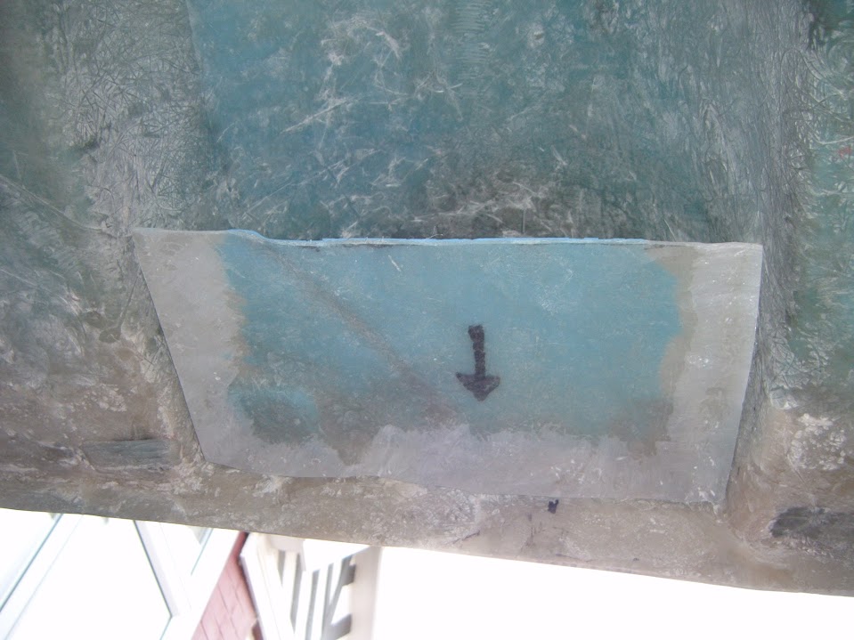
Note:
I am deliberately tucking this in a bit, so there is no risk of fouling against the framework.
( I will just use a bigger blob of bonding paste in this area. )
The panel was then taped into position.
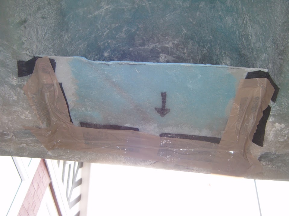
Before I started adding some fibreglass matting to seal/join the edges.
Not my neatest work, but given that I couldn't actually see what I was doing, not bad.

Although once this has set properly, I will tidy it up and add a final layer of matting across the joins.
- - - - - - - - - - - - - - - - - - - - - - - - - - - - - - -
The last job of the day was to double check the "latches" for the boot lid locks.
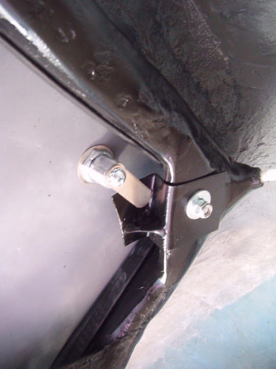
Thankfully they are work fine, so that is one less thing to worry about.
- - - - - - - - - - - - - - - - - - - - - - - - - - - - - - -
End of Part 1...