|
|
| Sammio Builds and discussions Sammio bodied car builds and specials |

28th December 2012, 09:04
|
 |
Senior Member
|
|
Join Date: Jul 2011
Posts: 5,328
|
|

Hi Paul, the viewing angle chart only applies to vehicles registered on or after 1st April 1986.
As even the youngest Spitfires rolled off the production line in 1980 and Vitesse and Herald production ceased almost a decade earlier it's safe to say that no Triumph based Sammio will need to comply with that diagram.
For our purposes Schedule 7 of The Road Vehicles Lighting Regulations 1989 have the following to say about the arrangement of indicators -
(b) A motor vehicle first used before 1st April 1986, a trailer manufactured before 1st October 1985, a pedal cycle, a horse-drawn vehicle and a vehicle drawn or propelled by hand:
Such that at least one (but not necessarily the same) indicator on each side is plainly visible to the rear in the case of a trailer and both to the front and rear in the case of any other vehicle.
Full details about lighting are available here -
http://www.legislation.gov.uk/uksi/1989/1796/made
It's worth trawling through and reading the small print as some of the regulations will affect some donors more than others. As an example, I can have a single rear brake light on my '68 based car, but you'd need a matched pair on the back of a Spitfire, Herald or Vitesse based car if the donor was built on or after 1st January 1971 (Schedule 12, part 1).
Happy reading! 

|
28th December 2012, 10:18
|
|
Senior Member
|
|
Join Date: Jul 2011
Posts: 5,328
|
|
Quote:
Originally Posted by CarNoob

thats one big scoop
|
Yes it is, although it doesn't look quite so big from normal viewing angles.
I had to make it that size to clear the thermostat housing in front of the rocker cover with the bonnet sitting where I wanted it. With the unmodified bonnet positioned to clear the top of the engine, the wheels looked completely wrong in the arches.
Before 
After 
A number of tolerances seem to have worked against me having a low profile bonnet - my engine seems to sit higher than most (wrong engine mounts?) and I fitted my body very low to try to get it to wrap under the off-side chassis rail, which it never quite did, meaning the back edge of the bonnet starts about an inch lower than it could've done.
The good thing about the Sammio design is that it can have various scoops, bulges etc added without ruining the looks (imho). After all, fifties race cars had scoops and bulges in the oddest places, just take a look at all the scoops and vents on this Lancia D24 -
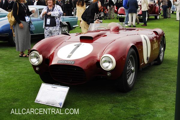
Nice. 
|
28th December 2012, 10:31
|
 |
Senior Member
|
|
Join Date: Feb 2012
Location: Wembley, London
Posts: 5,056
|
|
Mister Towed - Thanks, that is another great answer. 
So all I need to do now is mock up possible locations.
That is if it every stops raining long enough! 
Cheers, Paul.
|
1st January 2013, 14:23
|
|
Senior Member
|
|
Join Date: Feb 2012
Location: Wembley, London
Posts: 5,056
|
|
Whilst I thought I might have some free time after Christmas to work on my car, I was mistaken.
My time disappeared due to a combination of family time, my wife's birthday and the rain. *
But mainly I have been feeling pretty rough & under the weather with no energy at all. 
* Not my imagination, 2012 now officially the wettest year on record in England. 
So just a little bit of tinkering around the edges to report...
Rear Lighting Layout - Take 2:
I'd already taken a measurement between the rear seams when the kit first arrived.
So I knew the biggest area I would have to work with would be around 101 cm.

But I noticed something else when I was double checking this distance the other day.
The body work actually rolls inwards quite a bit at the outer edges like so...

Don't ask me how I missed this before when taping the lights onto the body. 
I think I was checking the lenses from above to see that sat squarely on the body itself.
The fact that there were not square to each other seems to have missed me for some reason.
The good news is Mr T's research (see above) shows they don't need to be in a set position.
So I will carry on regardless and the indicators will simply follow the lines of the body "roll".
However, I will bring the lights & reflectors a bit closer together than in the previous mock up.
Thus reducing how far out the indicators will be & so reducing the angle they will sit at.
I also went back to my previous research and re-discovered this Sammio layout.
Clearly if this managed to get an MOT, then I will have no problems with my lights. 
I simply used some brown paper to mark up some alternative "bunched up" layouts.
Note: The lights are supplied with a rubber edge that adds a few mm each side.
The thick blue lines represent the seams on the body work.
These photos show the following:
- 30mm between number plate & reflector, then remaining gaps at 20mm
- 20mm gaps throughout
- 20mm between number plate & reflector, then remaining gaps at 15mm
- 15mm gaps throughout


I'll have a think about which of these I think works best & then make a template for drilling holes.
Next Steps:
With a bit of luck I'll feel like going outside at the weekend if I get the chance.
Until then, "Happy New Year!", Paul.
Last edited by Paul L; 11th September 2019 at 08:44..
|
1st January 2013, 16:30
|
|
Senior Member
|
|
Join Date: Jul 2011
Posts: 5,328
|
|
Yep, the indicators just need to be visible from directly behind to comply with the vehicle lighting reg's for this age of car. I'll be taking a print out of the reg's with me to the MOT testing station come the day, just in case 
There's just one more thing though Paul (in a Columbo stylee) - it's probably best not to assume that the rear wing seams are equidistant from the centreline of the car. I wouldn't personally use them as a datum, I would find the true centreline and work my way outwards from there. Then do the final fitting up by eye, and if it looks right, go for it.
Good luck getting the look you want and I hope you have a great start to 2013. |
2nd January 2013, 17:10
|
|
Senior Member
|
|
Join Date: Feb 2012
Location: Wembley, London
Posts: 5,056
|
|
Mr T - Another good point about the centre line.
Funny how you can focus on the detail at one level & miss the bigger picture on another.
In which case, I will mark the centre point of the bodywork & align the template's centre point with that.
Thanks, Paul.
|
6th January 2013, 10:47
|
|
Senior Member
|
|
Join Date: Feb 2012
Location: Wembley, London
Posts: 5,056
|
|
In between taking down the Christmas decorations & other distractions, I've very little progress to report...
Front Indicators - Options:
I've previously posted photos of various front indicator options, so now it was time to mock up my own.
As the lens of my side repeater is not detachable, I needed a paper template to allow me to test locations.

After trying various options, this appears to be the best place for this 30mm diameter lens.
There is also just enough of a flat surface on the bonnet for the light to sit flush(ish).


I also test fitted my rear indicator lens (70mm diameter) for a quick comparison.
The increase in size meant the only flat surface it would fit flush against was lower down & pointing out.


Without wishing to sound too much like Goldilocks, I think one lens is too small & the other too big.
So I've just ordered a set of these Classic Mini indicators which are a bit smaller than the rear lens above.
I'll decide whether to construct a flat surface on the bonnet to mount them facing forward when they arrive.
( As I think they would look better it they aligned vertically with the headlights. )

With a bit of luck, and in the best fairy tale tradition, I hope these will be " Just Right". 
I will now use these side repeaters as there were originally intended on the side of the body shell.
Next Steps:
If the perpetual misty rain outside ever stops...
I hope to get one small job done today before we head out on a family trip.
Cheers, Paul.
Last edited by Paul L; 11th September 2019 at 08:46..
|
6th January 2013, 10:53
|
|
Senior Member
|
|
Join Date: Sep 2012
Posts: 424
|
|
get yourself a pringles tube,as its the right diameter. fibre glass the tube, once gone off cut a hole in your body the same diameter as tube, you can trim the tube inside the bodyand glass in . Once dried cut yourself a 12mm ply disc and glass in .Doing all of this will allow you to blend the raised tube into the bonnet with filler and shape up.
|
6th January 2013, 15:54
|
|
Senior Member
|
|
Join Date: Feb 2012
Location: Wembley, London
Posts: 5,056
|
|
Mikmiglia - Thanks for the tip Mike, always happy to get your feedback.
- - - - - - - - - - - - - - - - - - - - - - - - - - - - - - - -
I've got to be quick as we've just dropped the children off with Granny.
So my wife and I have got a night off and are heading out for a meal shortly.
Thankfully I had prepared the words in advance, just needed to upload the photos...
Front Grille Opening:
Initially I was going to wait until my grille arrived before cutting this hole.
However, in the end I was looking for simple jobs that wouldn't take too much time, or effort.
I had already paid for a steel loop with two hinge brackets to be bonded into my bonnet as an optional extra.
But this created an optical illusion which made the steel ring look like it was within the area to be cut out?
After some quick measurements I quickly realised I was simply being a bit dim.
Whilst this might looks like it is a flat surface on the inside, similar to the shape at the front ...

The hoop is on the inside the rim around the grille opening & the bonding material fills all the gaps. 

But I'm happy the "measure twice & cut once" school of construction did its job to spot my error.
So out came my drill to make some pilot holes & my jig saw to cut out the fibre glass from opening.
It was quite an awkward angle to get the jig saw blade into, so I removed the bottom guide plate.
I just need to smooth off the inside edges which are a bit rough and ready in places.


Until next time, take care, Paul.
Last edited by Paul L; 11th September 2019 at 08:48..
|
12th January 2013, 16:15
|
|
Senior Member
|
|
Join Date: Feb 2012
Location: Wembley, London
Posts: 5,056
|
|
I'm keen to mock up as much of the build as possible before I start permanently fixing things into place.
So today's little job was ....
Seat Belt Mounting Options:
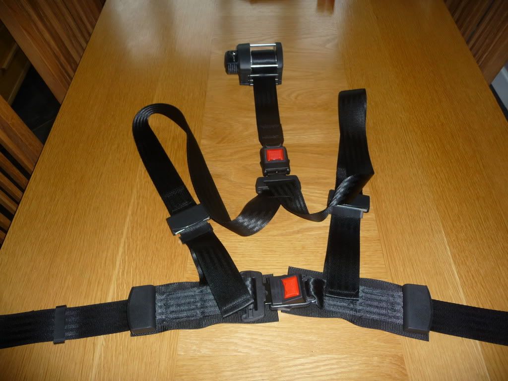
My donor came with brand new seat belts that I was keen to use if I could actually make them fit / work.
In my head I think of these as "3 point" seat belts, but they actually need four mounting points each.

I can re-use the original Spitfire mounting point next to the hand brake for the "Buckle" end.
I just need to drill a hole in the Cordite frame, which can wait until the frame is permanently bolted down.
Once I know these belts will work, I will remove the wiring currently in place for the warning light.
( A seat belt warning light is not a legal requirement & I've removed the associated wiring from the loom. )
This way, if these seat belts are not suitable, I can simply sell them on Ebay with the wires intact.


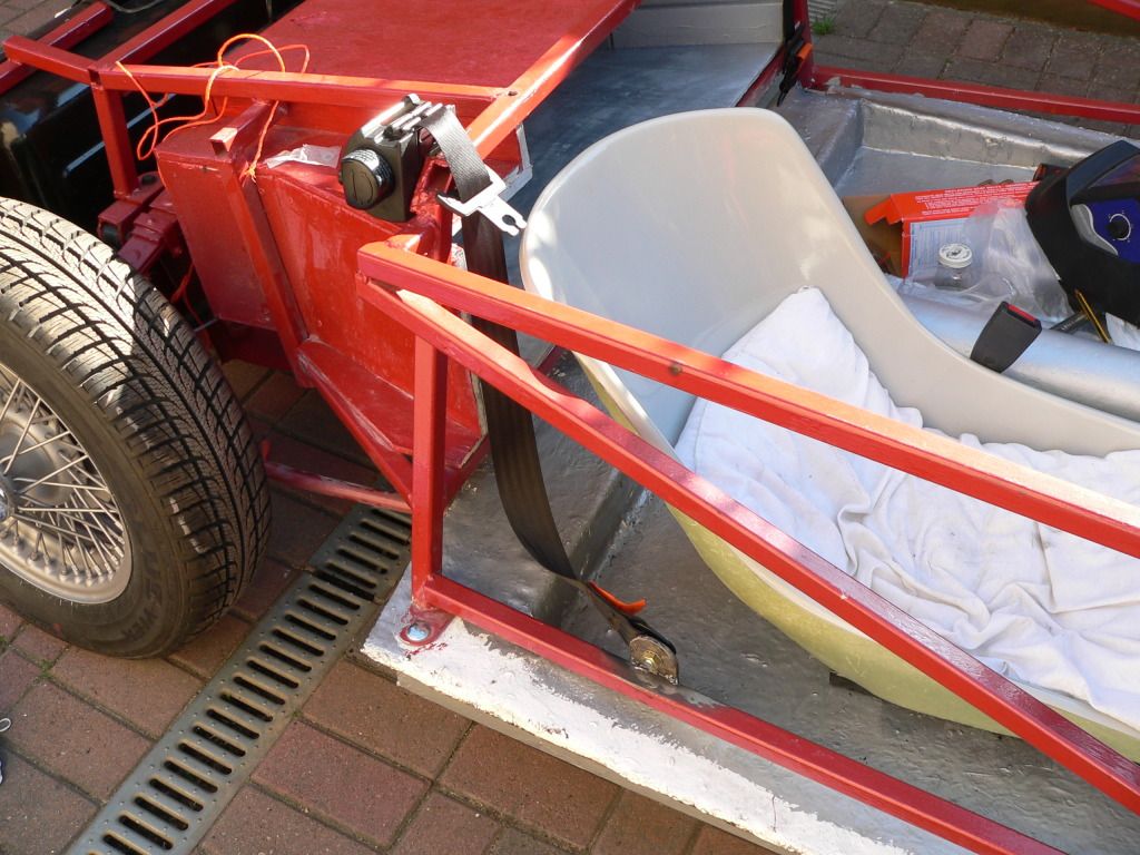
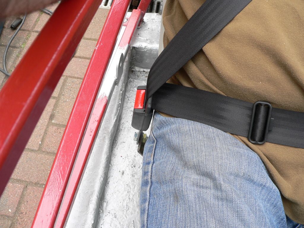
A mounting point for the "D Ring" was welded to my frame as an optional "extra" when I first ordered my kit.
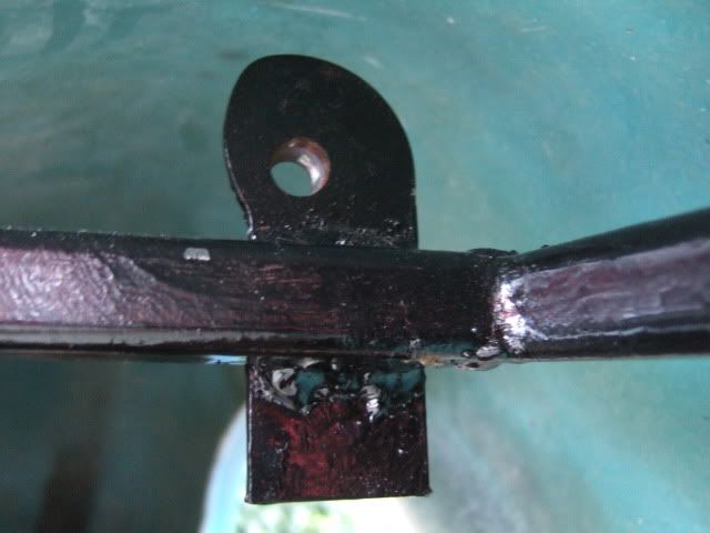

However, my test fitting threw up a few issues, which are easier to explain looking from the side.
The mounting bracket is to the left of the horizontal box section below.
Whereas, the rear cockpit plywood panel will be to the right of the vertical box section frame rail.
So there would need to be a significant recess in the rear panel to allow this to work as it is.
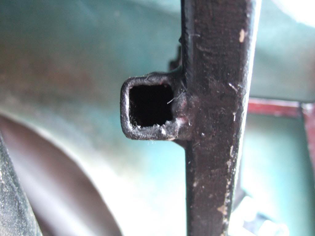
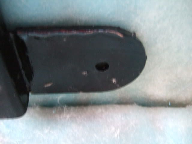
But before I started to worry about that, I turned my attention to the remaining lower mounting points.
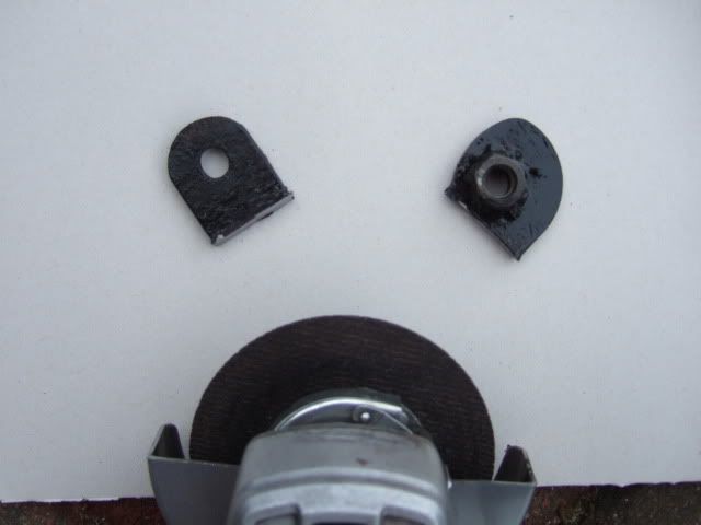
This is the bracket that was welded into place to do the job.
This has no retaining nut welded in place & was the wrong side of the frame to be of much use anyway.
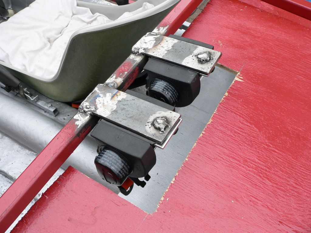
So I'd already bought some of these (2 of each) to do the job instead.

These will allow me to put the "Floor Mount" bracket on the inside of the cockpit framework.

The "Retractor" would need to be mounted through the rear cockpit panel.
This would give the belt a straight run to the "D Ring" without any twists in it.
Obviously, there would need to be a new bracket welded to the frame work to support it.

So at this stage I think it might be possible to use these belts, but I have some reservations.
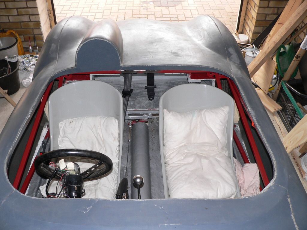
One big thing that was missing from this initial investigation was actually having a seat in place.
When I did fit the passenger floor pan & seat, there was very little room in the outside corner.
I was already considering "squaring" the inside edge of the cockpit like DaveCymru

But this photo also shows a very popular seat belt choice with a centre cockpit "feed".
I've also seen quite a few build with "static" 3 point belts and of course various racing harnesses.
So once again there is a bit of the proverbial beard scratching to do, before a final decision.
I will also revisit a few build threads as they make more sense when I reach that point in my own build.
I did discover something else significant while working with the seat belts, but I'll cover that in another post later on.
Until then, take care, Paul.
Last edited by Paul L; 11th September 2019 at 08:55..
|
12th January 2013, 19:13
|
|
Senior Member
|
|
Join Date: Jul 2011
Posts: 5,328
|
|
I wanted inertia reel seatbelts rather than racing harnesses and my original plan was to mount them in the standard position -
No matter what position I tried I couldn't work out a way of mounting them where they'd work and not risk being soaked in the wet or jammed by loose luggage behind the seats.
The curve of the cockpit corners makes it harder to fit them, and I didn't want to square the corners as I believe Dave C had problems with cracking in his. So, the simplest solution was to centre mount them and I think it adds to the quirkiness of the car.
Good luck and I hope you get them fitted where you want them. |
12th January 2013, 20:29
|
 |
Senior Member
|
|
Join Date: Jul 2011
Location: Marmande 47200
Posts: 501
|
|
If you want racing style but with inertia reel check out my thread I found full harnes fixed back to inertia single point.
Cheers pops
|
13th January 2013, 06:28
|
|
Senior Member
|
|
Join Date: Feb 2012
Location: Wembley, London
Posts: 5,056
|
|
Mr T - Outstanding reply.
Your constant support is one of the main reasons I am still chipping away at this project.
You have proved that all obstacles can be over come in the end.
I know you have worked on your own car for a long time, but it will be worth it.
Seeing you on the road will be great inspiration for the rest of us still building.
Pops - Thanks for the tip, I found the photo of your belts...
But I couldn't see one of them fitted?
Does the top buckle just stay connected behind the seat.
Also found Mr T's great link about seat belts on your build too...
http://assets.dft.gov.uk/publication...e-vehicles.pdf
Got to love this forum, cheers, Paul.
|
13th January 2013, 06:34
|
|
Senior Member
|
|
Join Date: Feb 2012
Location: Wembley, London
Posts: 5,056
|
|
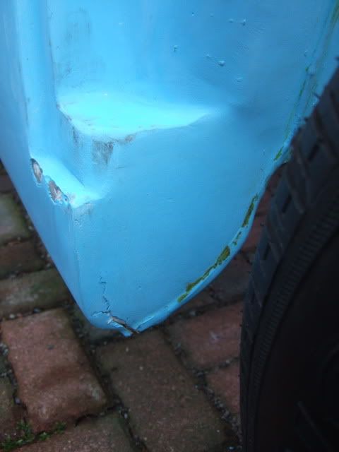
Just wanted to follow up on yesterday's post, as it had a knock on impact on this...
Frame & Bodywork - Take 3
The body shell has been resting on the frame work for a while now, but it hasn't "settled" any lower.
So I still had some issues with the driver's side not lining up the way I would have liked it to.
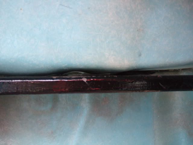
The good news is that whilst testing the seat belts I discovered one of the reasons for this...

Yes, the seat belt mounting bracket was fouling the bodywork on the driver's side.
This quickly settled any debate about whether, or not, I would try to use this bracket.
As out came the angle grinder, I then propped up the body & was quickly left with this.

I will remove the rest of the bracket when the body is off again properly.
While the angle grinder was out, I removed the lower seat belt bracket from the driver's side too.
As I've already trimmed the passenger floor pan to fit, the bracket on that side can wait.
I love the new Ribble approach of re-using the Spitfire body shell as it makes for an easier build.
However, that is no longer an option for me, so I will just make the most of what I have got.
So taking my frustrations out on the frame with an angle grinder was very therapeutic.
As there is no escaping the fact this frame work really is a [American Slang]POS[/Cussing]!
Note:
When Andy re-launches the Ribble Navigator (son of Cordite) these issues will be fixed.
Anyway, small rant out of the system and back to where removing this bracket got me...
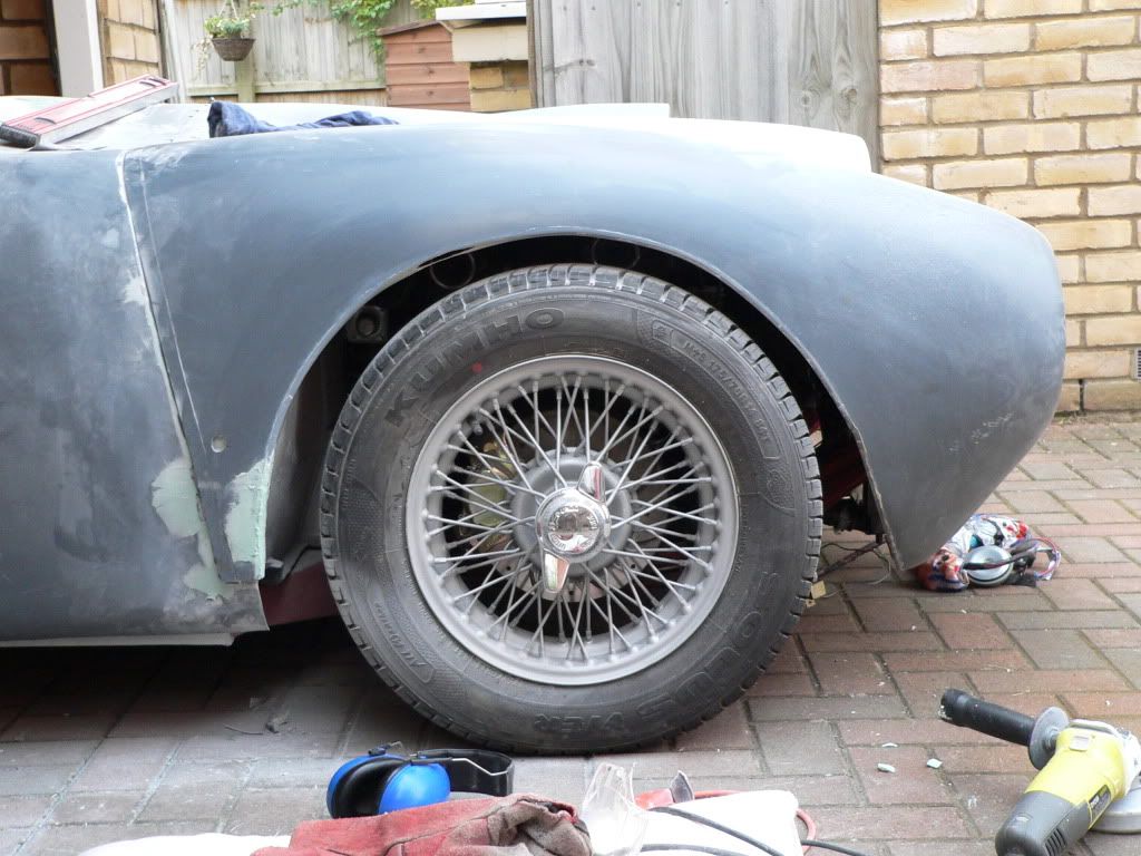
Instantly, I had a much better fit all round, the door cut out area was much better.

The side of the bodywork now just covered the lowest frame rail.
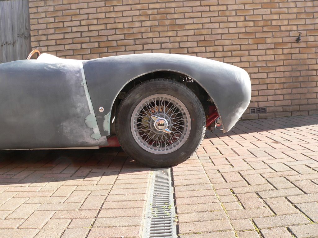
Before:

After:

The body also came a lot closer to the pedal mounting plate (more on this later).
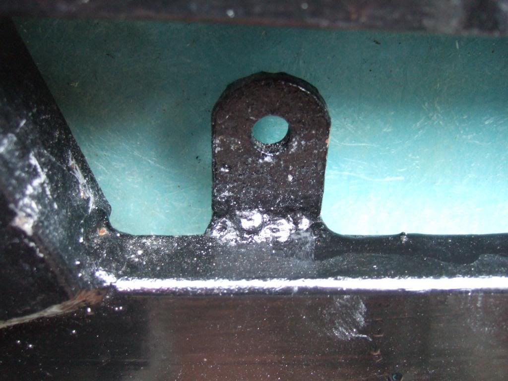
This just left the lower front corner on the driver's side as the remaining problem area.
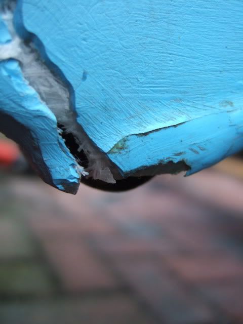
I think I will be able to reclaim a couple of mm by removing the bracket on the left of this photo.
 DonnySoutherner
 previously mentioned that this was surplus to requirements anyway.
It is to bolt the body shell to the frame, but it is next to the plate where the pedals are bolted on.
However, it does sit proud of the rest of the area which makes it the last point of contact.
I did have a go at getting the angle grinder in there without removing the body.
But there was just no room to play with & I just got a face full of sparks for my trouble!
Joking aside, I was grateful for the fact I did have safety glasses on.
Got some domestic stuff to do now, but hope to have more to post later today, Paul.
Last edited by Paul L; 11th September 2019 at 08:58..
|
13th January 2013, 10:36
|
|
Senior Member
|
|
Join Date: Jul 2011
Location: Marmande 47200
Posts: 501
|
|
Quote:
Originally Posted by Paul L
Mr T - Outstanding reply.
Pops - Thanks for the tip, I found the photo of your belts...
But I couldn't see one of them fitted?
Does the top buckle just stay connected behind the seat.
Got to love this forum, cheers, Paul.
|
Havent completed the fit out but can explain how it woks so far.
Inertia mounted on plates at the back of the framw, one in each corner, The drivers side one sits on top and roles within the rear of the hump.
The passengers side is underslung due to body clearance. This runs freely over the fuel tank and connects to the harness behind the rear panel of the cockpit with the two shoulder straps exiting where the body tub lips over the frame. This give me about 200mm of travel forward so can reach all the knobs etc.
tried other options such as anchoring behind the seats but the angles and lengths of belts just didnt work out.
When I am home in a couple of weeks I will post pictures which should explain a lot more clearly.
Pops |
13th January 2013, 11:29
|
|
Senior Member
|
|
Join Date: Feb 2012
Location: Wembley, London
Posts: 5,056
|
|
Just got time for another quick "copy & paste" update before heading out for a family pub lunch...
Brake Master Cylinder - More Thoughts:
You may recall, that unbeknown to me, the Cordite body was not designed for Spitfire 1500 brakes.

The more time I spend trying to work out how to keep these, the more of a pain it becomes.
All the brake pipes were refurbished by the previous owner.
The system was also tested to MOT standard (& passed) by my local garage.
So here is where my thought process has got me so far...
Option #1
Fit the master cylinder "as is" and adjust the frame, bulk head & bonnet to accommodate it.
Below is a rough sketch* of the impact of this approach on each of these areas.
( * Don't look too closely for anything resembling scale or true perspective. )

As you can see, a shed load of work and the distinct possibility of it looking like a dog's dinner.
So whilst this is a "don't fix want ain't broken" solution for the brakes, it is a no go for everything else.
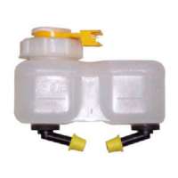
Option #2
Replace the existing brake fluid reservoir with a "remote" one mounted to the adjacent bulk head.
I would also cut out slots in the fibre glass to mount the m/c directly to the frame plate below.
( As this would lower the unit a few mm and they all count. )
The existing brake fluid "out" lines would remain unchanged and stay fixed where they are.
But new brake lines would be needed from the remote reservoir to the fluid "in" points.
Although more research is needed as I'm struggling to find out if this is actually possible.
I know the Spitfire reservoir can be removed, but think it is basically a plastic "push in" fitting.
So I need to check if you can get a hose fitting to match that isn't the normal "screw in" type.
I think this approach would allow me to make a much smaller modification to the bulk head.
The recess should sit in between the existing frame rails, so they wouldn't need any work.
Obviously the whole point of the system is to reduce the height, so the bonnet would be OK too.
 Option #3
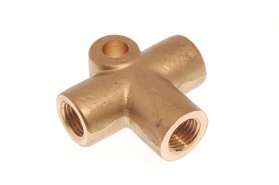
Replace the tandem master cylinder with an upgraded "traditional" single feed set up.
The twist would be to fit a "3 way" joint to keep the rest of the dual pipe work as is.
So the single pipe out from the new master cylinder would only be a few inches to the new joint.
 Option #4
Replace the m/c as in Option 3, but re-plumb the brake lines into a traditional line feed system.
Lots of pipe work required for this approach which is something I'm keen to avoid if possible.
Conclusion
I hope Option #2 will be possible, but realistically, Option #3 may be the most practical solution.
As always, happy to get feedback from those who know more about this than me.
Cheers, Paul.
Pops - Cheers Stuart, some photos would be a big help, thanks.
Last edited by Paul L; 11th September 2019 at 09:08..
|
13th January 2013, 17:35
|
|
Senior Member
|
|
Join Date: Jul 2011
Posts: 5,328
|
|
It'd be option 1 for me: Notching the frame isn't difficult, I had to modify mine to fit the instruments where I wanted them and recessing the bulkhead is also pretty straightforward; a fibreglass power bulge above the master cylinder wouldn't look out of place - a half sized American football would probably be about the right size to use as a former; and, above all, I'd want to be absolutely certain I had working brakes.
Oh, and I've even found a specialist company that sells purpose made 100mm formers to mould the power bulge from -
http://www.ebay.co.uk/itm/New-Dog-Sq...item3f1a46f215 |
13th January 2013, 19:51
|
|
Senior Member
|
|
Join Date: Jul 2011
Posts: 5,328
|
|
Good question Micha.
For our purposes the basics are:
Vehicle first used before 01/01/1965 - no belts required.
Vehicle first used between 01/01/1965 and 31/03/1981 - two point diagonal belts required for front seats.
Vehicles first used after 31/03/1981 - three point, lap and diagonal belts required for front seats.
http://assets.dft.gov.uk/publication...e-vehicles.pdf
The dates when you actually had to start wearing them are a little different, but, having limped away from a head-on crash on 1st April 1983, just four months after our law changed, I wouldn't want to be without one. |
14th January 2013, 18:13
|
|
Senior Member
|
|
Join Date: Feb 2012
Location: Wembley, London
Posts: 5,056
|
|
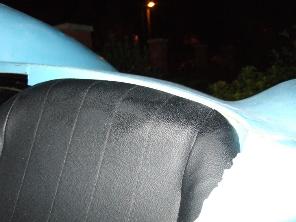
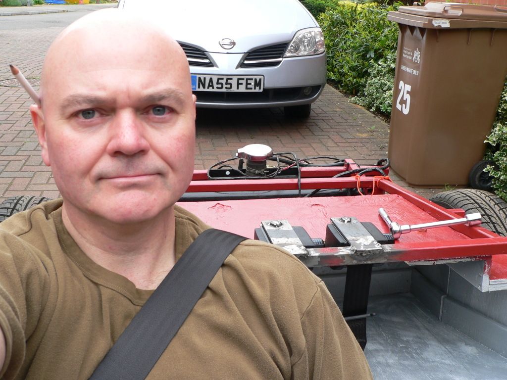
A Car For All Seasons...
This is what greeted me as I left for work this morning...

Still, at least the weather can't stop me shopping on line.
Rimmer Bros - January Sale
I had built up a list of assorted small bits & pieces I needed and this seemed like a good time to order them.
- All the retaining bits for end of throttle cable (previous clip went missing & was the wrong part anyway).
- Choke cable (as there is some fraying on the outer surround on my donor's one).
- Olive for petrol tank "fuel out" pipe (as I need to turn this through 180 degree, given the tanks new location).
- Clips for fuel & brake lines (easier to get these now rather than source them separately).
- A couple of small enamel Union Jacks which I plan to fit either side of the car (final location TBC).
However, I also made one significant purchase at this time, which I will cover in more detail below…
Engine Cooling - Update:
When I was looking at alternative brake master cylinders, one seller also did extra wide Spitfire radiators.
I went to compare prices with another seller I'd previously seen on Ebay but found his stock was sold out.
So by delaying a final decision (see below) I was now facing paying more for a reconditioned unit.
The good news is the Rimmer Bros sale put their new radiators under the price of the reconditioned one.
So I've now ordered this extra wide radiator which should simply "bolt straight in" to the Spitfire mountings.
Although I may need to get some longer hoses to connect it.
 Overall Project Planning:
When I started building this car I was half expecting other builders to be blazing a trail for me to follow.
The reality is not many Cordites are on the go & its Navigator replacement will have significant differences.
With limited time, I am keen to avoid having to re-do work, or do extra work which could have been avoided.
However, there comes a time where waiting for a perfect answer is no longer worth it due to knock on delays.
I'd delayed ordering this radiator because I still don't know if there is enough clearance under the bonnet.
( The bonnet will only fit when the front chassis brackets are removed after the re-body inspection. )
But the latest update on the original AndyP57 demonstrator is that he has abandoned the flip up bonnet.
Instead, he has cut out an access panel in the top of the bonnet, which will now be quick released instead.
It doesn't look like there will be any scoops, or bulges, but I just don't know if he needed to lower his radiator.

The other thing to note from this photo is that Andy has also abandoned the idea of using the original doors.
They have now been bonded / fibre glassed shut, which was my own "doomsday" option if all else fails.
( Andy's plan is to provide a better door arrangement for both the Navigator & Pilot (ex-Spyder) designs. )
With snow now replacing the traditional rain outside, I know I will be making slow progress over the Winter.
The key for me will be to finish as much of my "mock up" work as possible & make final build decisions.
That way, if we do actually get a half decent Spring & Summer this year I will in a position to push on.
Although given how long everything seems to take, I will not make any rash promises about deadlines.
Seat Belt Mounting Options - Update:
The new seats that were supplied with my donor didn't actually come with any instructions.
Thankfully Rimmer Bros were kind enough to send me some which I found shortly after my test fitting.
It looks like the "Retractor" and "Floor Mount" brackets could actually be bolted to the same mounting point.
So I will add that fact into the general beard scratching mix.

Until next time, take care, Paul.
Replies:
Mr T - I wouldn't mind an American Football shaped bulge in the middle of my bonnet if required.
It is the fact that it would need to be hanging half way off the edge of the bonnet that really worrys me.
And thanks for answering Micha's questions too.
micha - Welcome to my build thread.
I'm not worried about the V5Cs of the cars in the photos, the context was their front indicators, nothing else.
Legally my 1980 donor only needs a two point, diagonal, belt fitted, but I will be fitting something better.
If I can't get my own welding up to standard, I plan to get my mate to weld the seat belt mounting points.
Last edited by Paul L; 11th September 2019 at 09:09..
|
14th January 2013, 19:59
|
 |
Senior Member
|
|
Join Date: May 2011
Location: Somerset
Posts: 1,671
|
|
Quote:
Originally Posted by micha
interesting that most pictured cars on page 9 are still running on triumph herlad V5c´s
?
|
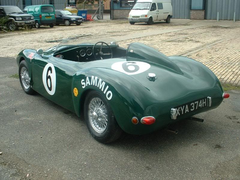
Seeing as it's panto season, and seeing as my old car is one of the ones in question, i feel like wrapping up this conundrum for you. :
(assume panto voice)
"oh no they're not!"
If you're basing your statement on what is shown on one of the on-line sites (e.g. http://www.carcheckuk.co.uk/) to check those reg numbers then i can prove 100% from personal experience that what is on the physical V5 and what Swansea hold can be different to what they show on their sites!
i.e. i know 100% that at least my old car and Trevors old car (48) both say Sammio Spyder on the V5's, yet on that checker mine still shows up as a Herald!
That's just one of the joys of classic and kit cars
Now back to our main feature....... |
|
Currently Active Users Viewing This Thread: 9 (0 members and 9 guests)
|
|
|
 Posting Rules
|
You may not post new threads
You may not post replies
You may not post attachments
You may not edit your posts
HTML code is Off
|
|
|
All times are GMT +0. The time now is 12:16.
|


 Linear Mode

