|
|
| Sammio Builds and discussions Sammio bodied car builds and specials |

30th September 2012, 06:54
|
 |
Senior Member
|
|
Join Date: Oct 2011
Location: Surrey
Posts: 363
|
|
 But square to what?
As others have suggested this week and how we aligned our frames and body we established a centre line, both front to back and side to side.
Which enabled us to half any differences so rather than bolt one side and have 20mm short the other we +10mm & -10mm the difference and were able to line the frames centre to the chassis/body.
Hope that helps and does state the bloody obvious.
Impressed by your level of workmanship and approach all with out a garage? to you have a workshop? winters coming.
|
30th September 2012, 07:44
|
 |
Senior Member
|
|
Join Date: Jun 2012
Location: Luton
Posts: 133
|
|
Quote:
Originally Posted by Paul L

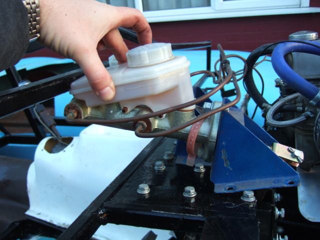
Brake Master Cylinder:
I knew I had some issues with fitting this in the fibre glass bulkhead.
But today it became clear that I'd missed another problem which is the frame itself.
If the pedal mounting plate stays where it is the back of the M/C will hit the frame. 
|
If you go the remote reservoir route the it looks like the cylinder will go in if you mount it horizontally. The cylinder bracket would need modifying along with the pedal above the pivot (to keep the pushrod geometry correct). Not difficult if you're confident in your welding. |
30th September 2012, 08:10
|
 |
Senior Member
|
|
Join Date: Jul 2011
Posts: 5,328
|
|
I'd be inclined to modify the frame (and bonnet if necessary) to accommodate the brake master cylinder and resovoir in their standard positions. The frame only supports the bodywork and provides brackets to hang things from, it isn't part of the chassis structure so it won't cause any safety issues with the handling etc, even if your welds fail. But if your brake pedal shears off...
I cut and re-welded my frame just to allow my instruments to go where I wanted them -
Good luck finding a solution that works for your set-up.  |
30th September 2012, 18:40
|
 |
Senior Member
|
|
Join Date: Feb 2012
Location: Wembley, London
Posts: 5,056
|
|
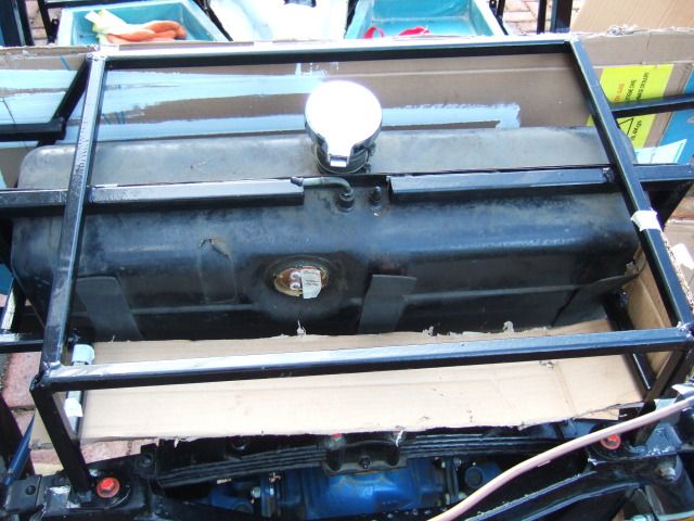
Family day today, but was able to grab a few minutes before the sun went down.
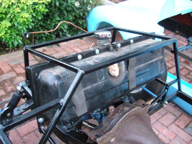
Petrol Tank:
As part of my frame test fitting & general "mock up" I rested the petrol tank in place.
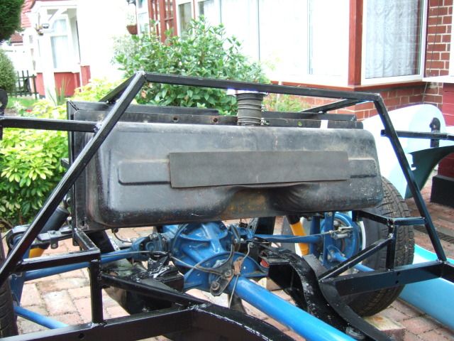
If I align the tank with the bottom of the frame work, the fuel line feed fouls the frame.
I know this can be adjusted, but I didn't have to worry about that as there was a bigger issue.
With the tank at the bottom, the mounting points at the 4 corners didn't line up with the frame.
So I lifted the tank so it was flush with the top edge of the frame instead.
This will allow me to use the 4 mounting holes on the top edge of the tank.
( Which means the fuel line feed pipe is also clear as is. )
The bottom 2 corner mounting points can also be used as they line up with the frame.
Which just leaves the top 2 corners not being used as the are too far out of alignment.
I think there were only 5 bolts holding it originally, so 6 bolts should do it (touch wood).
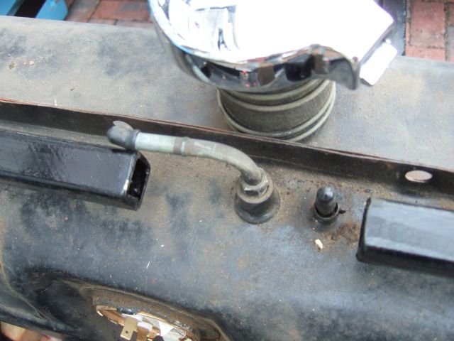
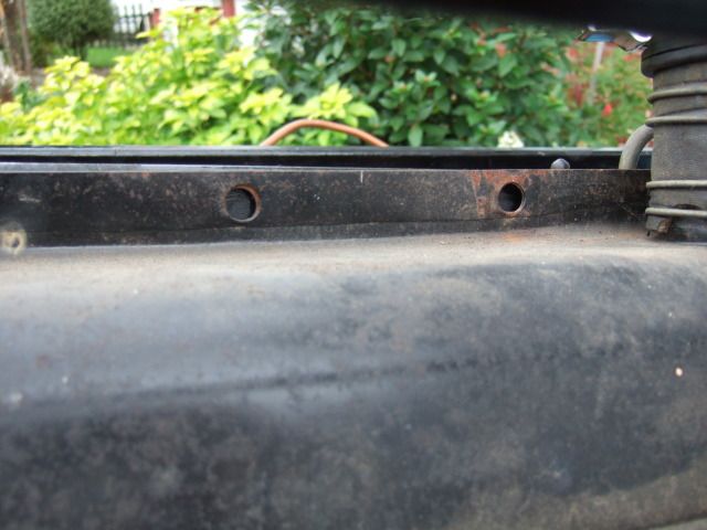
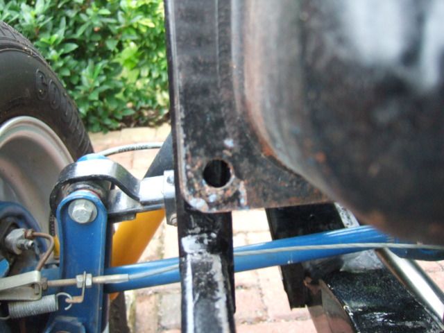
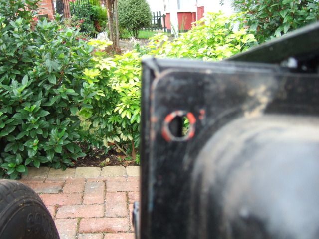
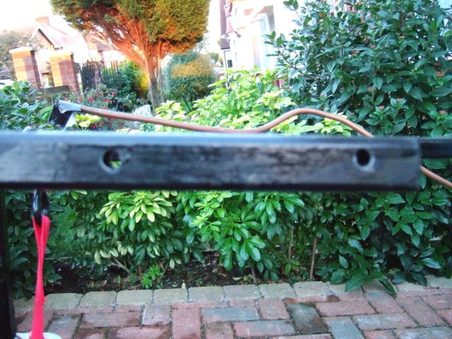
Hand Brake Mounting Panel:
There is still plenty of room behind the petrol tank for my 2nd hand panel to fit under.
It is sitting very high in the photo below as I still have to trim off the bottom edges.
I need to be very careful when I take the angle grinder to this panel.
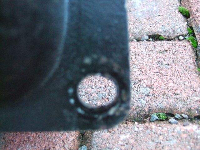
Thankfully I remembered what the bolt hole in this photo is for before I started cutting...
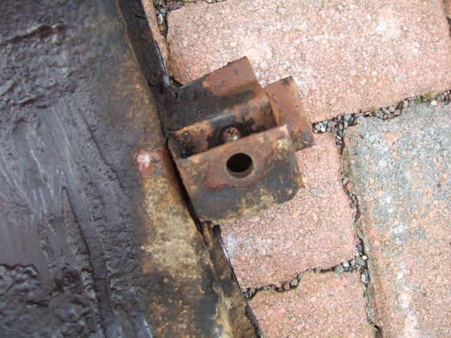
It is the pivot mount for the hand brake mechanism & I'd have been stuffed without it!
Cheers, Paul.  Replies:
Charman.Tech
Replies:
Charman.Tech - I think centre lines will be a big help in convincing me things are straight.
I will be putting the chassis on stands before I do my final bolting together to get it level.
A sloping driveway is not a big help when it comes to lining things up. 
Unfortunately I don't have a workshop either & do fear winter!
"Clean" jobs like wiring I can bring indoors, or use the Summer House in our garden.
But everything else has to be done outdoors which really wastes time.
Its the bringing out & putting away of all tools, parts, etc. that is a real pain.
Currently the body & bonnet are just left along side while I work on the frame.
 MoriniMan
 - Currently I have no welding skills at all, but I know two good mates who do.
I am currently making a list of questions to get their advice on before I make any final decisions.
Mister Towed - I'd already noted the way you re-arranged the frame behind your dash.
Which is why your build thread is such a great source of information to me. 
The more detail there is the better as far as I am concerned (which explains this thread too).

|
30th September 2012, 19:03
|
|
Senior Member
|
|
Join Date: Jun 2012
Location: Luton
Posts: 133
|
|
Quote:
Originally Posted by Paul L
MoriniMan - Currently I have no welding skills at all, but I know two good mates who do.
I am currently making a list of questions to get their advice on before I make any final decisions.
|
I've built complete pedal assemblies from scratch, so modifying a pedal hold no fears. I'd be happy to help. I've lost count of the number of Triumph pedals I've welded up and re-drilled to repair wear. |
2nd October 2012, 21:04
|
|
Senior Member
|
|
Join Date: Feb 2012
Location: Wembley, London
Posts: 5,056
|
|
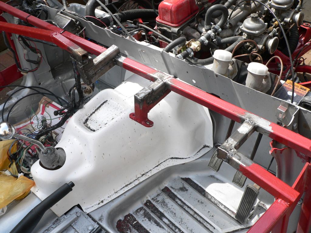
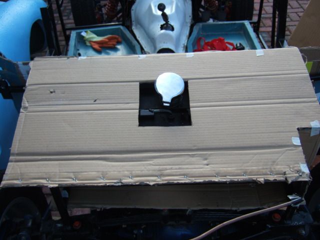
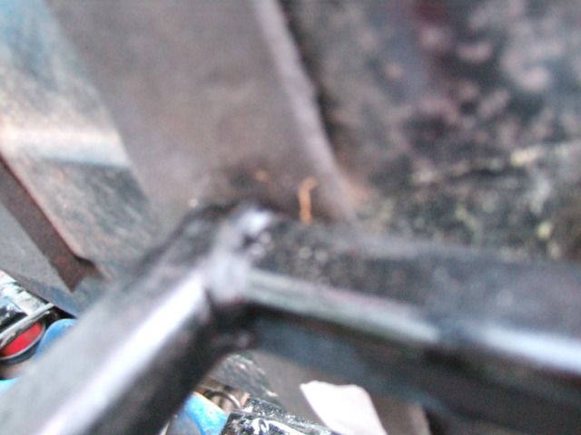
Pedal Mounting Plate - Part 2:
Despite taking an extra photo of the area, I forgot to mention this in my last post.
The front ends of the pedal mountings stick out beyond the edge of the mounting plate / framework.
I haven't test fitted the body since mounting these, but I think they require more room than is available.
( Note: They were only mounted so I could sort out the holes & will be removed again soon. )
I remembered DonnySoutherner having some sort of pedal clearance issues on his build.
So I re-read the thread and he had to cut the front of the pedal mounting brackets off.
Quote - Modified pedal bracket (front cut away otherwise won't fit).
The only other photos I've seen of this area come from AndyP57's demonstrator build.
I can see his pedals are also mounted from above & do not use the front bulk head bolts.


Either way, I'm pretty sure that 6 bolts through the metal plate will be more than enough to hold them.
I just need to decide whether the pedal mounts or the bulkhead will need to be "adjusted".
Plywood Panels:
I ended up using a spreadsheet to layout the maximum size of each cockpit panel required....
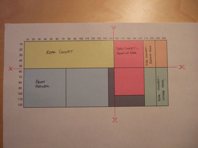
It looks like they will all fit on a single large sheet (2.44m x 1.22m) with a little bit left over.
There also some handy "cut here" points that will leave me with 4 sections that will fit in my car.
I'll make more accurate cardboard templates when the time comes to take account of the "fiddly bits".
I'll also double check my measurements to ensure I haven't made a howling error in the layout.
I also realised that I was mixing up Exterior ply with Marine ply and they are not quite the same thing.
I might post a question on the forum about the various ways different builders have sealed their panels.
Cheers, Paul.
Replies:
MoriniMan - Thanks for the offer, I will definitely give you a shout if I get stuck.
|
6th October 2012, 19:32
|
|
Senior Member
|
|
Join Date: Feb 2012
Location: Wembley, London
Posts: 5,056
|
|
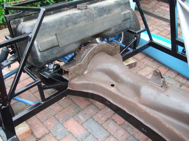
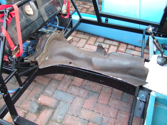
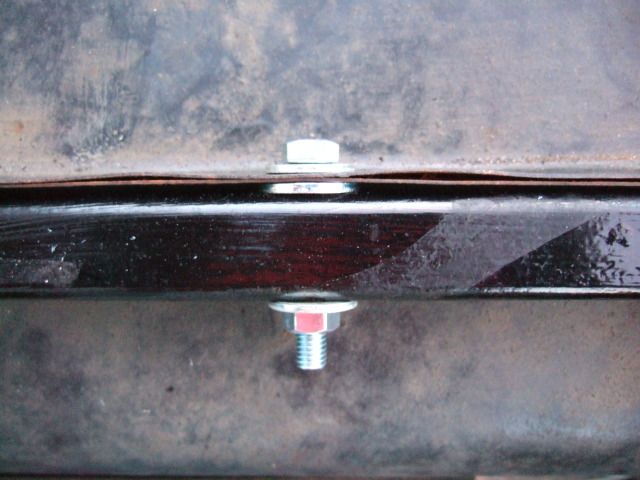
Petrol Tank:
I put some tape on the frame to mark the holes required to hold the petrol tank in place.
I will then centre these holes (top to bottom) in the frame to maximise metal around them.
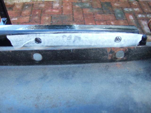
I need to extend the mounting holes at the bottom corners of the tank.
This will then allow me to drill holes in the middle of the frame for better support.
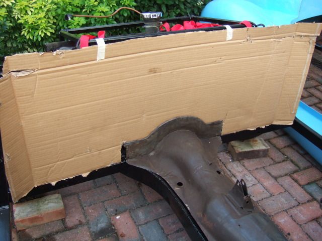
Plywood Panels - Continued:
I did re-measure the cockpit panel sizes & I'm now happy that my previous pattern/layout will work.
( I had added a generous safety margin to each measurement to ensure I had enough. )
So I moved on to looking at the area behind the rear cockpit panel to see what might work.
I wanted to have some basic protection for the petrol tank & some sort of rear arch structure too.
The other thing I wanted to do was provide additional support for the area behind the seats.
This follows the photo of Misted Towed's Incredible Bonding Blob! ...
His logic was that people will instinctively lift themselves out of the car by pressing down on the body.
That makes sense to me, so I plan to do something similar, although I will not have a luggage box.
There is however a handy four sided shape of frame work above the Cordite petrol tank...
If you compare the two photos, the petrol tank is much closer in the Cordite vs. the Spyder layout.
I guess this should not be a real surprise as one started with 2 seats & the other with 4.
I just played around with some cardboard to see what would fit where.
Until I refit the body for further testing, I'm not sure how much clearance I have over this area.
So one option would be to rest a panel on top of the frame which would provide the support required.
Although I would have to leave some sort of hole for the filler pipe.
One option would be to put panels around most of the tank by following the shape of the frame work...
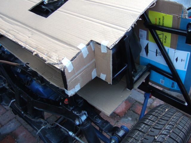
I tested cardboard below the frame for under the petrol tank, but there will be a gap above the frame.
These wooden wedges are slightly bigger than the gap that will be available (tank will not be at an angle).
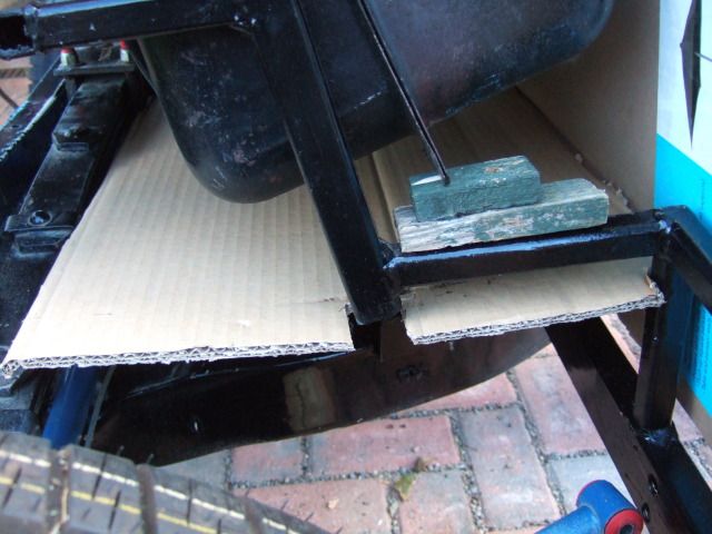
So more beard scratching required before I decide on a final layout.
Mock Up:
The whole point of looking at things now is to avoid problems in the future.
Another area that has caught my eye is the clutch pedal clearance.
I know it is not currently connected, but the pedal hits the front foot well.
And that is before I build this up with the panel required to tie this in with the body.
( As per AndyP57's demonstrator build. )

I will temporarily re-connect the clutch to test this again another day.
Only then will I know if it is an issue or not.
Especially as lowering the pedal mounting plate was one solution to my brake M/C problem.
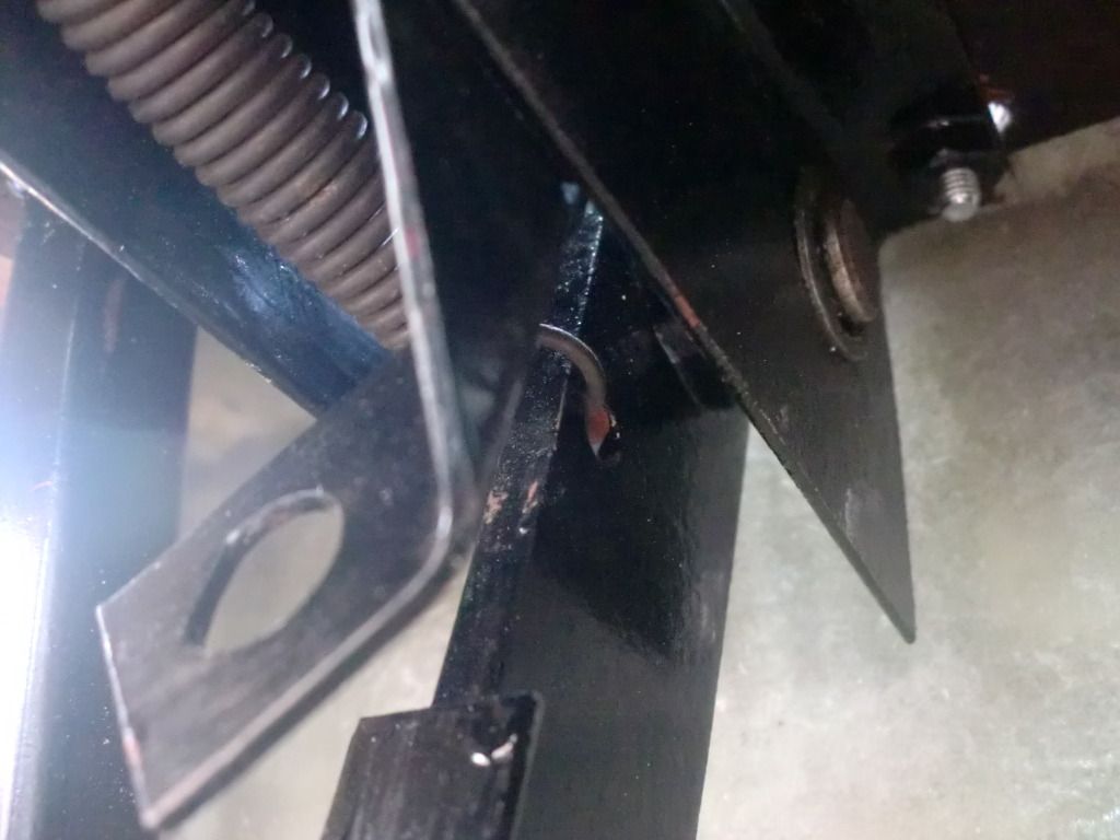
Hand Brake Mounting Panel:
Having only just realised the significance of the bolt hole in this panel...
Imagine my despair when it fell off after a very innocuous knock while moving it.
I will add this to my list of welding jobs required and sort it out another day.
The only good news is that it came away now and not during my first MOT test.
Despite the small set back, I decided to continue preparing this panel for use.
First step was taking my angle grinder to the excess metal forming the lower "lip".
This will allow the panel to sit flush with the Cordite fame work and my lowered floor pans.
Then I needed to cut out small sections from the rear to allow for the Cordite frame work.
I didn't want to use the grinder after 6 pm, so I will test fit & finish these cut outs tomorrow.
 Engine Re-Starting:
I am very conscious that the last time I had my Spitfire engine running was 21st July.
After that I had to disconnect everything so that I was able to remove the body shell.
It is also clear that a lot of work is required to get the car to even a 'Go Kart'/'Moon Rover' stage.
So I will have a little think about the minimum requirement to restart the engine in a few weeks.
Hopefully this will reduce the chances of any problems associated with leaving the car outside.
Off the top of my head, this will involve the following tasks:
- Battery - Need to establish where I will earth this to & extend cables if required.
- Ignition - Don't need to have steering in place, just have section of column with the key handy.
- Wiring - Just re-connect the minimum number of wires for the engine to run.
- Choke & Throttle Cables - Just need to be connected at the engine end & be 'pullable'.
- Petrol - I need a temporary arrangement until the frame is fixed in & hard line re-routed.
Overall Progress:
I am trying to remain positive and remember that every hour worked is an hour closer to finishing.
However, I also have to accept that this project is going to required a significant number of hours.
Still, with a bit of luck, I'll get a few of those hours in tomorrow.
Cheers, Paul.
|
6th October 2012, 20:38
|
|
Senior Member
|
|
Join Date: Jul 2011
Posts: 5,328
|
|
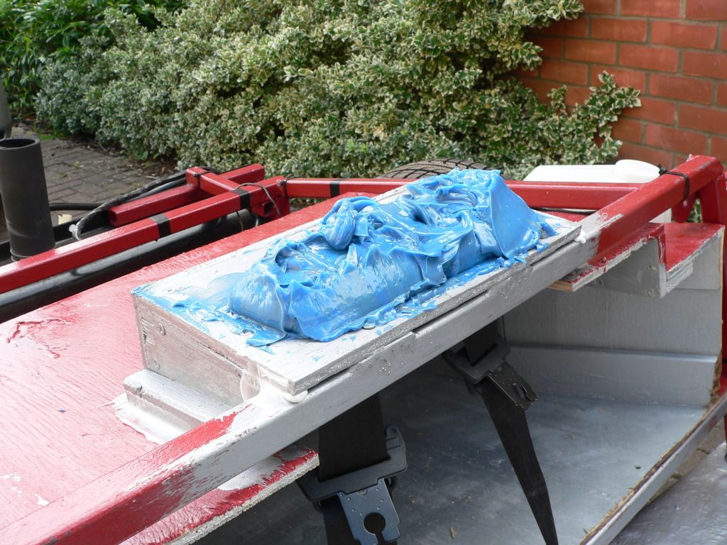
That's the spirit Paul - all progress is a step in the right direction. From Sammio building experience, even when the progress involves deciding to undo a week's work and change direction completely, like I did with my dash mounted handbrake that I couldn't make work, it's still a step towards finishing the car the way you want it.
I'm very happy with my bonding paste blob under the rear deck. It's exactly where you naturally put your hand when you climb in and if you leave that panel flexible the paint's bound to crack sooner or later. With it properly supported you can get in and out with confidence.
Btw, I modified my Spyder frame away from stadard spec. quite a bit at the back end - the fuel tank usually sits where my luggage bay is, between the rear bulkhead and rear spring - but mine sits in a fabricated frame behind the rear axle. Can't see anyone modifying a Caterham frame like that somehow...
Anyway, keep plugging away and before you know it, like me, you'll be at the point where your car's roadworthy. Almost.
|
7th October 2012, 07:48
|
 |
Senior Member
|
|
Join Date: Dec 2011
Posts: 656
|
|
Hi Paul, Just one thing I've noticed is that you have your tank mounted the original way. I've mounted mine backwards so that the fuel filler goes in the gap in the frame, the feed is forward of it and the sender is accessible through a hole in the bulkhead. In practice, should make no difference to operation but for a supportability aspect, makes it easier should anything go wrong.
|
7th October 2012, 17:27
|
|
Senior Member
|
|
Join Date: Feb 2012
Location: Wembley, London
Posts: 5,056
|
|
We decided to have a family "lazy day" today, so lots of just hanging out & then going out for lunch.
Despite having to oil the garden furniture before covering it for the winter I did get a some time on the car.
Petrol Tank - Take 2:
Following AndyP57's comments I swapped the tank around & the petrol cap is in a better position.
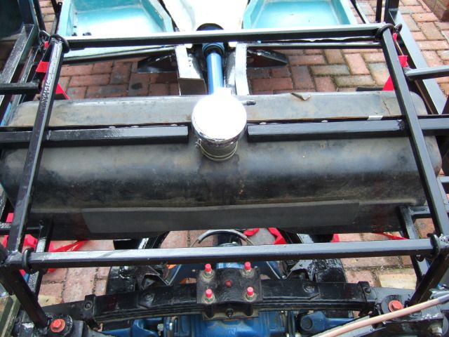
I had tried it in this position before, but couldn't remember why I didn't stick with it.
Then I noticed the tank hits the frame in one corner & this is why I swapped it around the first time.
However, I can get around this by adding a few washers when bolting top of the tank to the frame.
This would give me the small clearance I need to fit an original rubber strip in between tank & frame.
Hand Brake Mounting Panel - Continued:
This is the part of the frame that I needed to make cut outs from the panel to clear.
In an attempt to remove the least amount of metal possible I made this a much harder job.
I have to do my angle grinding at the bottom of the garden behind the summer house.
This avoids sending sparks over nearby cars if I did it in the front drive.
It also avoids me sending sparks on to the washing hanging on the line.
So I was back & forth from the drive to the bottom of the garden like a yo-yo.
I should have just taken a huge chuck out right from the start and been done with it!
Anyway, I ended up with cut outs like this on either side of the panel (excuse poor photo).
This allow the panel to sit flush in position over the Cordite framework.
Which in turn gives me a rough idea of how the rear cockpit panel might eventually look.
 Mock Up - Continued:
Previously I had this reply from Dave...
Quote:
Originally Posted by davecymru
... the only bit that was an unknown for me was how to join my gearbox cover to the tunnel i had made, so it may be worth having a play and fabricating a basic solution while you've still got everything apart as when the body is on you end up doing some superb contortions when 'fettling' the interior ... |
As I now look at the hand brake mounting panel, it seems longer that my original.
This is the gap between gearbox cover and the panel now:
But this was the gap before:

I was hoping to re-use the metal "bridge" between the two pieces.
So that is something I will keep an eye on when things are in their final positions.
As I said before, the whole point of testing things now is to see how it all fits together.
Until next time, take care, Paul.
Replies:
Mr T: - Thanks for the encouragement, you are living proof that chipping away works.
I had forgotten that you moved your petrol tank, but I will still copy your big blob idea.
AndyP57 - Thanks for the tip, I have taken your advice (see above).
If you ever get the chance to read back over some of my other posts, I'd value your input.
There are many things I don't want to mess up, like using rubber frame mounts, etc.
|
14th October 2012, 18:13
|
|
Senior Member
|
|
Join Date: Feb 2012
Location: Wembley, London
Posts: 5,056
|
|
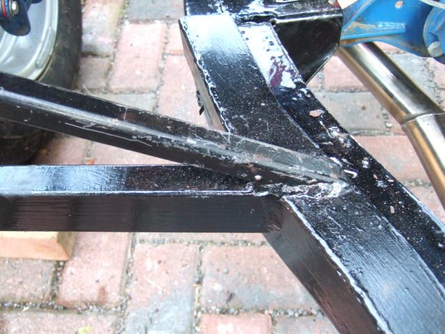
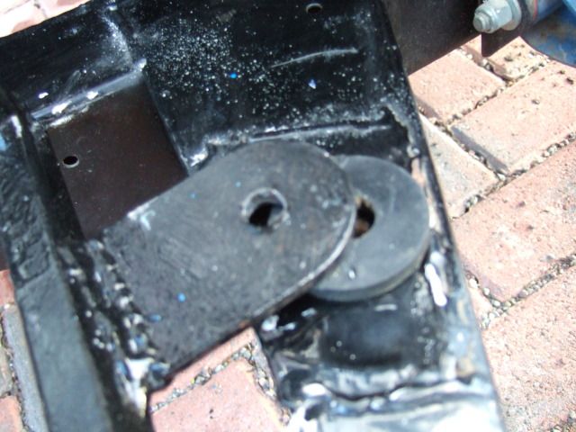
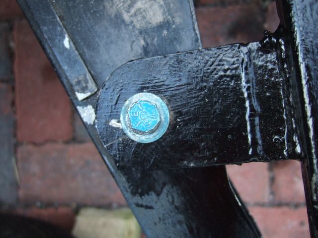
Internal Framework:
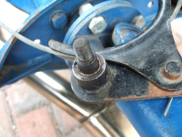
I fitted the radius arm brackets to the frame to ensure the spacing at this end was OK.
Driver's side went in with no problems, but the passenger side turned into a right 'mare.
My first issue was the holes in the frame were too close together...
But that was a simple job to fix by running a drill bit through the holes to widen them.
However, I just couldn't get the bolt through the bracket, bush & out the other side for ages.
I think I worked my way through the complete 'Profanisaurus' until I final got it in.
This would have been a 5 minute job with an extra pair of hands, but took me over an hour.
Still at least I ended up with both arms in place at the end.
Note:
Big adjustable spanner was one of my many 'leverage' tools, not used for tightening nuts!
I decided to join the top sections of the two frames together before I attempted to fix the front frame.
In the absence of any official guidance, I've assumed that the straight edges of both frames should line up.
So I took the plunge and drilled holes through each side of the rear frame and bolted both sides together.
Passenger Side:
Driver's Side:
Then I turned my attention to the front section of framework that had initially come up a bit short...
So I tried a little bit of gentle persuasion using nothing more than a pair of ratchet tie down straps.
I hooked one end to the Cordite frame & the other to the main cross rail at the front of the chassis.
I then tighten each strap alternatively one notch at a time to spread the tension more evenly (ish).
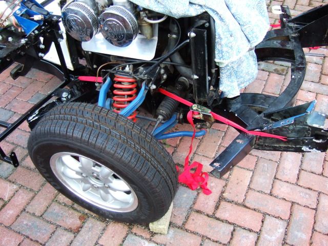
This approach initially seemed to be working & the passenger side finally slotted in to place.
I had to re-use one of the Spitfire's metal chassis / body shell washers on top of a rubber one.
But the driver's side wouldn't line up for love, nor money, despite more quotes from the 'Profanisaurus'.
In the end, I had to admit defeat and drill another hole in the frame and bolt it in as best I could.
It was only when I went to slacken off the straps that one ratchet "exploded" under the tension... oops.
"So don't try this at home kids." 
I know I still need to take some measurements to ensure the frame is sitting square on the chassis.
But I'm happy enough that is fits for now so that I can at least have another go at fitting the body.
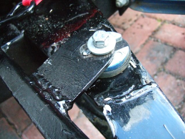
I removed the straps holding the petrol tank in place to elongate the bottom corner mounting holes.
Excuse the poor photo...
I then put the tank back in place & adjusted it to give a best fit along the top edge & bottom corners.
I put some new tape on the frame & re-marked the holes required & then removed the tanks again.
( It occurred to me that is wasn't a good idea to centre holes in the frame independently of the tank. )
Then I drilled the 6 holes required in the frame...
I've used some normal nuts on the bolts for now, just to hold the tank in place for now.
After I finish test fitting stuff, I'll remove it again & paint it & then use Nyloc nuts to secure it.
I put extra washers on the driver's side to give me the clearance I need between tank & frame.
Again, excuse the poor photo...
As always I never seem to get as much done as I hoped to do.
But the motto of this build is any progress in better than no progress.
Until next time, take care, Paul.
|
14th October 2012, 18:31
|
|
Senior Member
|
|
Join Date: Jun 2011
Location: birchington, kent
Posts: 1,769
|
|
As always, enjoying your thread... Very detailed.
|
14th October 2012, 18:40
|
|
Senior Member
|
|
Join Date: Jul 2011
Posts: 5,328
|
|
As with most things Sammio, fitting the frame is subject to sod's law - if the frame's square, then the chassis probably isn't, and if the chassis's square, you can guess the rest.
Take one small step at a time though and giant leaps are possible...
|
15th October 2012, 08:07
|
|
Senior Member
|
|
Join Date: Mar 2012
Posts: 1,152
|
|
Thanks for the great detail. It's really useful and interesting. Keep chipping away. No minute is truly wasted......it just feels like it sometimes!
|
21st October 2012, 15:54
|
|
Senior Member
|
|
Join Date: Feb 2012
Location: Wembley, London
Posts: 5,056
|
|
Bloody Weather...
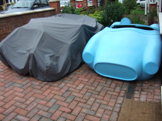
I've resigned myself to rain getting in the way of my build, but now the wind is picking on me too.
Came home during the week to find the wind had tried to rip the car cover off my rolling chassis.
The straps were pulled either side of the framework to between the wheels, turning the cover into a kite.
This resulted in a huge rip across the top of the cover, which I had to patch back together with tape.
 Under The Weather Too...
I am currently being fuelled by Beechams and Lucazade as I try to fend of a bug of some sort.
So I've had to rest this weekend and avoid 'playing' outside with the car.
However, despite being on 'restricted duties', I could still get some small stuff done...
Petrol Tank Venting:
I posted a question about the venting pipe in my petrol tank & my filler cap here.
The last think I want to do is find out I've missed something simple late on in the build.
Shopping Update:
I put a small order in with Rimmer Bros.
- 2 x Headlight adjustment sets (The originals were letting down my restored headlight assemblies).
- Brake pedal stop light switch (After I managed to break my donor's original one ).
I went to B&Q Watford to pick up two 2.44 m x 1.22 m x 9 mm sheets of exterior plywood.
This was the nearest 'Superstore' that would cut the sheets into four for me.

This meant they fitted into the car with no real issues.

I cut them both the same size based on my previous layout for the cockpit area.
I know I haven't worked out what I need for the other panels yet, but I should be OK.
I've also started to order my first batch of construction materials.
- 3.5 Litres of U-Pol 'Easy One" body filler.
- Two lots of 2" x 10 metres heat wrap exhaust pipe bandage with metal ties.
I'm still working through Mister Towed's feedback to pick the following:
- Bonding paste.
- Fibreglass stuff.
- Extra resin to seal the plywood panels.
When that is ordered I think I will have more than enough to get me started anyway.
Ebay Update:
I hope to get my last remaining Spitfire donor parts on sale on Ebay shortly.
There just seems to have been other stuff getting in the way of me organising this before now.
Whilst I originally hoped to end up with a "free" donor, I am now quite relaxed about the net cost to me.
I know some builds have actually made a profit on their donors and I salute them for this.
Headlights:
One final "indoor" job that I was able to do was make a template for the headlight rubber seals.
Another simple "Blue Peter" job of cutting out a cardboard cereal box to the right size.

I will use this to ensure the holes in the bonnet for the headlights are cut out in the right place.
It will also show me where to drill two larger holes for the headlight adjustment screws.
I will leave the holes to mount the headlight themselves until I offer up the shell to the bonnet.
Next Steps:
Keep taking the medication and have another early night so that I recover ASAP.
Until next time, take care, Paul.
Replies:
GaryH & Oxford1360 - Thanks gents, hopefully this helps potential builders see what is involved.
I know I find the detail in other build threads helps me to work out what I am supposed to be doing!
Mr T - You are right about expecting a bit of give & take between the chassis & frame.
Mind you, from your experiences, there will probably be some give & take in the body shell & bonnet too!
Last edited by Paul L; 10th September 2019 at 09:43..
|
27th October 2012, 10:42
|
|
Senior Member
|
|
Join Date: Feb 2012
Location: Wembley, London
Posts: 5,056
|
|
Restricted Duties:
I'm still trying to fully recover from the bugs that are conspiring to strike me down.
But I do hope to spend a bit of time on the car this weekend, I'll just need to wrap up warm.
So here is a very quick catch up until I have something better to report...
Project Time Line:
My project has now passed...
- 6 months since I bought my donor
- 4 months since the kit arrived
- 3 months since the engine last started
Not sure how many actual hours I have managed to put in during that time, but clearly not enough.
I quickly abandoned my initial idea of keeping an accurate log of hours worked as it took too long!
But the real question is how many hours can I put in during the next 6 months now that winter is coming?
I am conscious that I am in a bit of a holding pattern at the moment while I try to form a cunning build plan.
Mind you, I can't actually finish my 'mock up' work until my floor pans arrive (something Andy is working on).
I also want to ensure my "To Do" list covers everything, but more importantly, that it is done in the right order.
My time is limited, so the last thing I want to do is undo any completed work because I missed something.
For example, I will check the clutch pedal (see previous post) before bonding in the front foot well.
As it will be much easier to fix any potential clearance issues while parts are simply resting in place.
The good news story on my project plan is there is not much to do on the Spitfire rolling chassis.
The main job will be fitting the rear spring lowering block, which I think will be required, but still TBC.
Everything else was done by the previous owner, I don't even need to buy things like brake pads.
Shopping Update:
All the stuff I ordered last week has arrived (apart from one headlight adjuster kit on back order)...

I also bought a second hand Renault Megane header tank from Ebay during the week & that's here too.

This will be used as the traditional Sammio "fix" for connecting the original heater pipes without an air lock.
I'd like to order a wider, high performance radiator, but want to see the space available under the bonnet first.
I've also finally ordered the things I need to start bonding & fibre glassing my Cordite together.
I used the same supplier as Mister Towed, Glasplies, and they were very friendly over the phone.
Hopefully there is now a big box on its way with the following inside:
- 2.5kg of bonding paste
- 5kg fibre glass CSM roll 600 gsm (approx. 8 sqm)
- 2 x 5kg of lay up resin (for first batch of fibreglass work & to seal my plywood panels)
( The resin is supplied with a separate catalyst )
- Plus application rollers, acetone cleaner, measuring syringe, etc.
When I have a better idea of how much fibre glass I will be using, I might need some more resin.
But as 5kg was the smallest roll size they do, I've got more that enough to get started.
I've also just bought an old AA badge off Ebay like the ones others have fitted to their Sammios.
I know it seems odd to buy something for a grill that is also still on the 'missing in action' list.
But I am convincing myself that every job I complete, no matter how small, is still progress.
"Hump" Head Rest:
Great explanation & photo from Mister Towed on how a padded head rest would be attached.
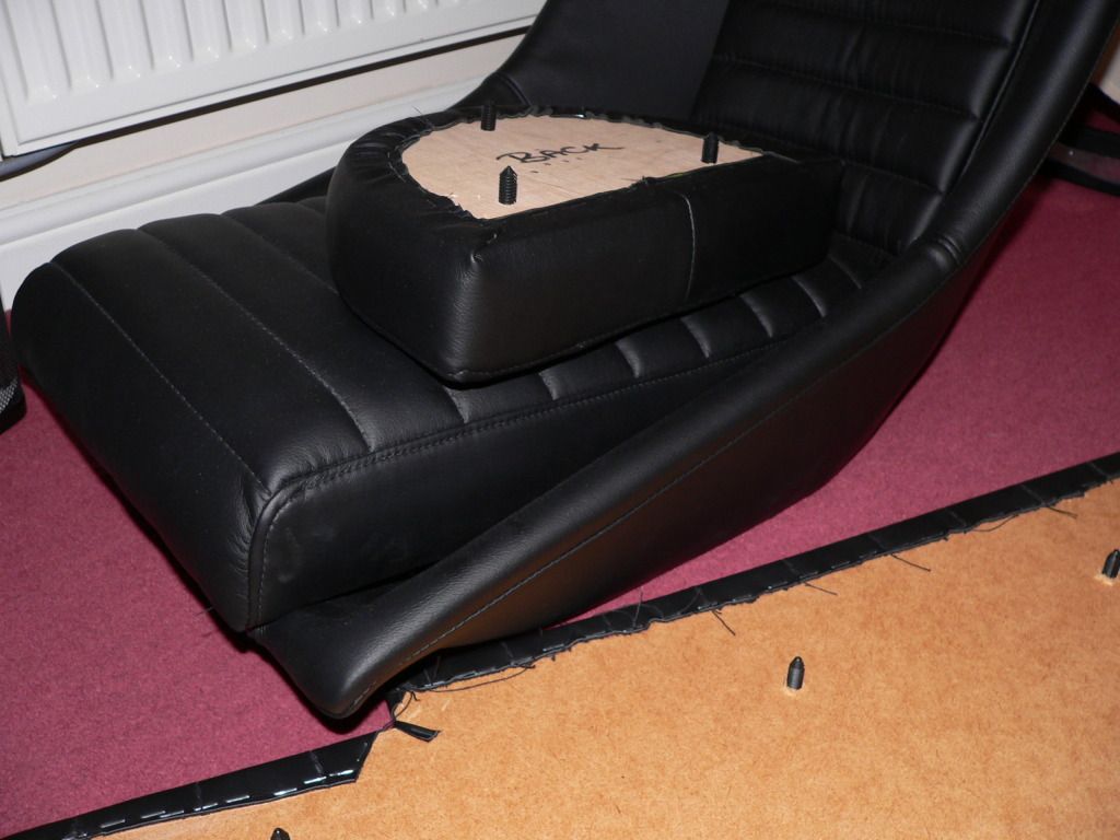
Issues with the original Sammio trimmer at the time I ordered meant I didn't order one with my kit.
If I do decide to have one, I'll give these trimmers a call as they have done great work for Mr T.
Battery:
I plan to attempt to re-start my engine within the next few weeks, so I've got my battery on charge.

Quick Question:
Would it be OK to use a jump lead as a temporary earth cable just to start the engine?
I still need to finalise my new earthing point, the cable routing & therefore the length of cable required.
Next Steps:
I'd like to start lowering the fuel & brake lines along the main chassis beam.
As this would bring me closer to being able to finish bolting the frame in place.
Hopefully I'll have a better update before the weekend is out.
Cheers, Paul.
Last edited by Paul L; 10th September 2019 at 09:43..
|
30th October 2012, 15:35
|
|
Senior Member
|
|
Join Date: Feb 2012
Location: Wembley, London
Posts: 5,056
|
|
Last Weekend's Result:
Annoying Virus 1, Cordite Building 0.
Despite my best intentions, I had to admit defeat & spent most of the weekend sleeping, or resting.
At least I was able to use the internet & I also watched 'A car is born' (recorded from TV) for inspiration.
Being stuck indoors also let me work on a photo submission for the 2013 Sammio calendar.
Obviously it will not be a finished car, but I'll post a copy of the photo here in the next day, or so.
I'm now off work for a few days to spend half term with my family.
I will not get a chance to do much before the weekend, but I did grab a few minutes earlier...
Clutch Pedal Clearance:
Previously, my 'mock up' / test fitting of parts highlighted a possible issue with the clutch pedal.
It appeared to hit the front foot well panel, but at the time it was not connected to the clutch.

So I undid all the bolts temporarily holding the pedal bracket to the Cordite frame work.
Then I put them back in, this time bolting the clutch master cylinder bracket into place too.
After reconnecting the end of the pedal to the M/C, I had a working clutch pedal once more.

Now, I could see how far the pedal moved under normal working operation conditions.
The bad news is that not only does the pedal still hit the front foot well...
It would also go as far as the frame itself with the foot well removed completely.

And that is before you add the extra layer of plywood on top to join the panel to the body.
So I think there needs to be a bit of the proverbial beard scratching to find a solution.
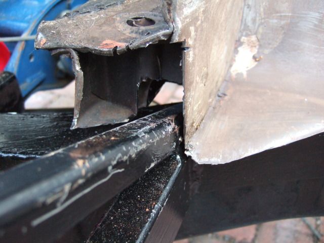
Brake Master Cylinder:
I knew I had clearance issues with the M/C, but the brake pedal may also foul like the clutch.
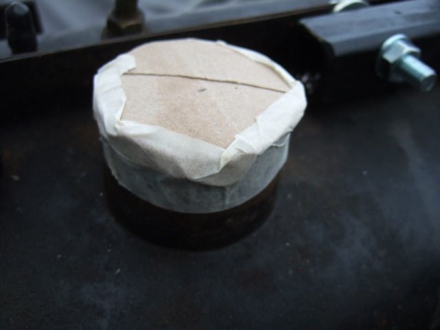
Anyway, one problem at a time, and I made a cardboard cut out to match the height of the M/C.
The M/C length would only fit if the frame behind the dash board was cut & re-joined around it.
Something similar to the job Mister Towed did on his frame to accommodate his instruments.
( See photo in his reply above. )
However, I will still need 4 cm from the top of the front frame to the top of the M/C.

So I will see what space I have to play with when I do my next test fit of the body shell.
But I have a rotten feeling there is no way this will clear without some sort of bulge fitted.
And that may have to cover both the bonnet & bulkhead which would be tricky.
Shopping Update:
Well at least my fibre glass stuff has now arrived, so I have the stuff needed build a bulge.
But there were some serious fumes coming from the boxes (thankfully no leaks, I checked).
So I had to quickly shift them to the garden shed and leave the windows open to air the house.
I passed the shed today and it smells like there is a glue sniffers convention going on inside!
Until next time, take care, Paul.
Last edited by Paul L; 10th September 2019 at 09:47..
|
3rd November 2012, 14:40
|
|
Senior Member
|
|
Join Date: Feb 2012
Location: Wembley, London
Posts: 5,056
|
|
Cordite Body Fitting - Take 2:
There were a few small issues during my first attempt to test fit the body.
Although in fairness, most of them stemmed from my use of zips ties to hold the frame in place.
This time, I was at least aware some of my "mock up" work might also get in the way.
So first of all I removed the filler cap & connecting hose from the top of the petrol tank.
At least I remembered to cover the hole in the tank so I couldn't drop anything into it by accident.
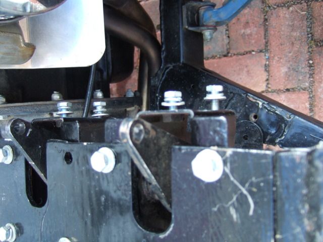
I also removed all the clutch & brake pedal mounting brackets from the front of the frame work.
Then, once again, I needed to rope in my wife to help me lift the body shell into place over the frame.
Our approach is to get the bulk head in place first with the rear end in the air, then drop the rear down.
It started raining before we could fine tune the fit, so I was left to get wet putting the cover back on.
That was on Wednesday, we then spent Thursday & Friday in York as our family half term trip.
So today was the first chance I had to have another go at finishing the test fitting process...
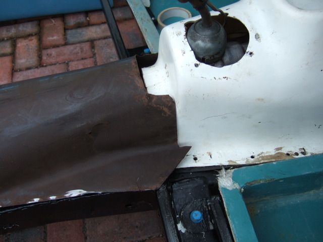
The bulk head was hitting the front mounting plates of the frame on both sides.

I took some comfort from the fact AndyP57 also trimmed his Cordite demonstrator's body to fit it.
( Although I am not actually sure what bits he had to trim. )
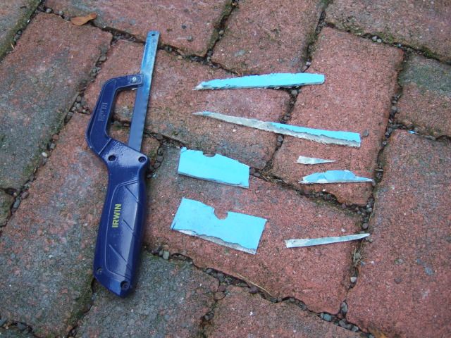
So I started by cutting two vertical lines in the bulk head either side of these brackets.
I then drilled a hole between to get my hacksaw blade in to make a joining horizontal cut.
This allowed the body shell to drop down further at the front bulk head.

But as the body shell was dropping other parts of it would foul something else.
So I continued to cut little slithers of fibreglass off here and there, but not much in total.
The passenger side now fits very well as you can see by the door cut out in the frame.

However, the driver's side refuses to play ball and remains out by just a few mm.
The body work around the door cut off is not as low as on the passenger side.

As far as I can tell this is due to the bulk head hitting the pedal mounting plate.
Which seems to be the only reason it will not go any lower on the driver's side.
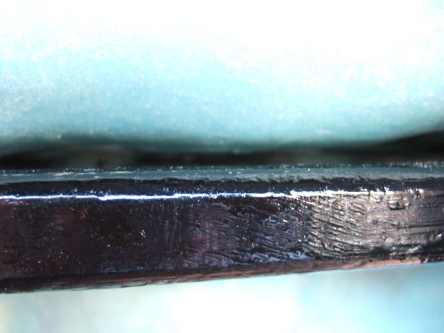
Which in turn means the body shell will not cover the bottom of the front frame work.
As I said before, there is only a few mm of the frame visible on the driver's side.

Although the front corner of the frame work also sticks out below the body shell.
My attempts to get this corner to fit also resulted in a small crack in the fibre glass. 
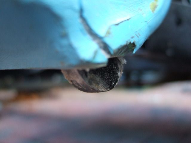
I will leave it like this for know and then have a think about the best solution.
It is the front corner section I need to resolve as the side section isn't an issue.
( I could easily use body filler / fibre glass to extend the side over the frame. )
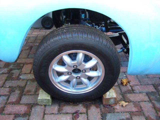
Either way, the body is sitting much better than it did first time around.
Unfortunately, my front garden wall stops me taking a side on photo.
So here is the rear wheel taken from above which gives an odd view.
 2013 Sammio Calendar - Photo Submission:
You may have seen these already, but I got the idea after being stuck indoors.
Not sure if these will make the final cut, but it was just a bit of fun for "October".
It would be nice if I could submit a photo of my finished car for the 2014 calendar. 

 Lowered Floor Pans:
You may have seen Andy's announcement regarding Cordite production here.
Before he left for a well earned holiday he confirmed my floor pans are on their way.
This will allow me to test fit my seats and sort out the seat belt mounting points.
This in turn will allow me to start working on the plywood panels for the cockpit.
So these really are keys parts of the kit and I can't wait to see them.
Next Steps:
After working in the cold this morning, I quickly remembered that I am still not 100%.
So I will be having a bit of a rest before hopefully doing some more work later.
Until next time, take care, Paul.
Last edited by Paul L; 10th September 2019 at 09:54..
|
3rd November 2012, 19:21
|
|
Senior Member
|
|
Join Date: Jul 2011
Posts: 5,328
|
|
As the corner of your frame is visible under the driver's side, it looks like the Cordite bodies are also a bit shorter on the offside than the nearside, just like the Spyder. I eventually decided to paint the side rail the same colour as the car so it doesn't show so much -
Without sectioning the body and adding a fillet I couldn't think of another way around this one 
The thing to always remember with Sammios is that nobody will ever see the car from both sides at the same time, so the, ahem, little idiosyncrasies won't stand out.  |
3rd November 2012, 21:41
|
|
Senior Member
|
|
Join Date: Jul 2011
Location: Belgium
Posts: 103
|
|
Bear in mind also that in the era that inspired the Sammio's design, similar cars would be hand built and often differ quite considerably left to right. As long as it was fast, they wouldn't worry much about symmetry!
Baz from Brussels
|
|
Currently Active Users Viewing This Thread: 7 (0 members and 7 guests)
|
|
|
 Posting Rules
|
You may not post new threads
You may not post replies
You may not post attachments
You may not edit your posts
HTML code is Off
|
|
|
All times are GMT +0. The time now is 07:06.
|


 Linear Mode

