|
|
| Marlin 5exi builds Calling all you sexi builders....sorry 5exi builders, show us your progress. |

5th January 2008, 20:41
|
 |
Senior Member
Enthusiast
|
|
Join Date: Nov 2007
Location: Somerset
Posts: 232
|
|
 Electrical wiring
Okay first may I say thanks to MarlinTurbo for an interested 3 hour chat over the bonnet of a 5EXi, picked up a few pointer there…
As its cold in the garage I thought I would familiarise myself with the wiring loom. It’s now stretched out on the dinning room floor and I am slowly identifying and placing labels on the identified ends. I have not done many yet!
The basic diagram supplied does not include the colours for the codes and I am at a loss to understand what UW, RU, UG, SB, NY GU, RU, NG or KU stand for in the international colour coding!
I assume ‘LT G N’ means ‘Light green with an N stripe’?
I have Johns scanned book images but that does not help too much and John’s wiring list but that only adds to the detail and does not connect it all up.
(there are tooo many John’ss on this forum!)
My next thought is to rummage in the RAVE CD to identify circuit colour codes and expect there to be some correlation matching up to John’s ‘Rover - Marlin colour differences’.
Anybody got a better understanding than me or an A0 diagram of the intended layout (joke), no but I would pay money for that diagram if it exists…..
eaa53
Last edited by eaa53; 5th January 2008 at 20:42..
Reason: spelling
|
5th January 2008, 21:48
|
|
Senior Member
Enthusiast
|
|
Join Date: Aug 2007
Location: Saxmundham,Suffolk
Posts: 167
|
|
Quote:
Originally Posted by eaa53

The basic diagram supplied does not include the colours for the codes and I am at a loss to understand what UW, RU, UG, SB, NY GU, RU, NG or KU stand for in the international colour coding!
|
I knew all those lessons learning wiring colours too many years ago would come in handy sometime. So assuming it follows standard they should be:
B = Black
G = Green
K = Pink
L = Light
N = Brown
O = Orange
P = Purple
R = Red
S = Grey
U = Blue
W = White
Y = Yellow
Therefore the following should be the case
UW = Blue with a white stripe
RU = Red with a Blue stripe
UG = Blue with a Green stripe
SB = Grey with a Black stripe
NY = Brown with a Yellow stripe
GU = Green with a Blue stripe
RU = Red with a Blue Stripe
NG = Brown with a Green Stripe
KU = Pink with a Blue Stripe
Quote:
Originally Posted by eaa53
I assume ‘LT G N’ means ‘Light green with an N stripe’?
|
It should be Light Green with a Brown Stripe
Quote:
Originally Posted by eaa53
(there are tooo many John’ss on this forum!)
|
Or the other way to look at is that it makes life simpler when replying, if you cant remember the real name behind the username go for John and you have a 50% chance of being correct 

|
5th January 2008, 23:58
|
 |
Senior Member
Enthusiast
|
|
Join Date: Jul 2005
Location: Dorset
Posts: 1,180
|
|
I'm sure there are divided opinions on this, but I deemed the wires a bit under specified on the loom (I hate dim headlights), so I binned it, and started from scratch. I did initially CAD my wiring diagram, but that was incredibly tiresome so scapped that route, and just cracked on with the wiring.
Ric H, Jerry, and Craig have all done the wiring from scratch too. Jerry's is a bit unique though, as every wire is black!
|
6th January 2008, 07:05
|
 |
Senior Member
Enthusiast
|
|
Join Date: Oct 2004
Location: Basildon, Essex
Posts: 1,800
|
|
Quote:
Originally Posted by eaa53
Anybody got a better understanding than me or an A0 diagram of the intended layout (joke), no but I would pay money for that diagram if it exists…..
eaa53
|
You may be joking, but I have an A3 book with all the diagrams in that I bought. It has the pages coated so you can draw on them and rub them off.
I'll see if I can dig it out as I don't use it anymore.
Ah the wiring. Get used to it. Once it's all connected up, there's the tidying. Treat the electrials as different electrical projects. Engine managment, Hazard (this is more complex than you think), wiper (you may want intermittent for example. Let me know if you do).
Engine managment. Parts you need are: Marlin loom, Fuse box from the mk3 bubble ( it has the engine managment fuses etc.), little black 4 relay box. Then connect up to ECU and engine look.
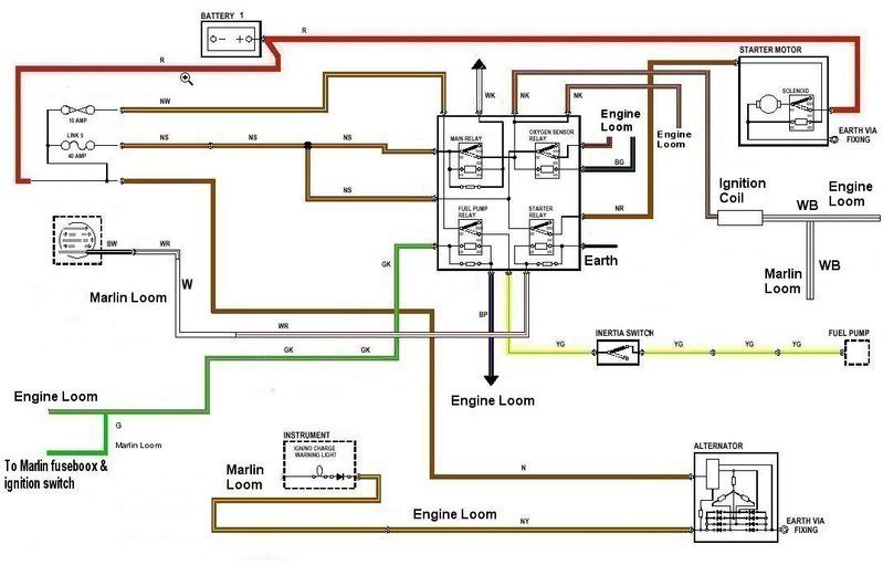
The wire going to look on the right of the oxygen sensor relay (engine loom), is brown/blue.
Here is the ignition switch wiring:
http://johns-5exi.delta-sin.co.uk/ign%20switch.doc
Excuse the pun. But should get you started!
Let me know if you get stuck.
|
6th January 2008, 07:50
|
 |
Senior Member
Enthusiast
|
|
Join Date: Feb 2006
Posts: 351
|
|
Guys
I as some of you know built the 1600 K series, and to the best of my understanding, at the time the loom was designed around that. I must say initially I was some what perplexed, but I laid the loom as said on the floor in the warm of my living room on a cold winter’s night, and with help from my partner we ladled it up. When I started there was some confusion, and perhaps more that a bit of apprehension, I hope he does not mind me bigging him up, but John (Limpabit) was very helpful, and provided some good suggestions.
From my perspective more so, the loom was a lot of money for something not much, and after seeing the loom from my previous kit car, albeit about £100 more, it was evident it was made by an electrician. I made some alterations to the loom, including enlarging some of the main power wires, my decision only based around the rover donor conductor size.
I must say using the Marlin colours in conjunction with the Rover manual was great help, but to be honest I felt I had to put to much effort into this, and more should have come out of the documentation provided, although for me, in the end I did enjoy the wiring side of the build.
In the main the loom was ok for the purpose it was designed for, for my car, but hopefully with feedback from customers, now that Marlin are responding, any suggested improvements will be taken on board.
Steve
|
6th January 2008, 08:02
|
|
Senior Member
Enthusiast
|
|
Join Date: Oct 2004
Location: Basildon, Essex
Posts: 1,800
|
|
Quote:
Originally Posted by SDMC001
From my perspective more so, the loom was a lot of money for something not much, and after seeing the loom from my previous kit car, albeit about £100 more, it was evident it was made by an electrician. I made some alterations to the loom, including enlarging some of the main power wires, my decision only based around the rover donor conductor size.
|
Hi guys.
I must admit. The size of the wires (very small) was a concern to me. Ian's used thicker wire while I just went with the flow on mine and used the standard wiring from the Marlin loom and trusted Marlin. I have no worries now with the Marlin loom. Because after investigation, and having to buy new wires (after the accident), the thin can take the current. I was always at the belief that thicker wire = more current. But the thinner stuff is rated at far greater current that I was expecting.
For example.
http://www.vehicle-wiring-products.e...e/thinwall.php
I bought some headlights wire rated at I think it was 25A. May have been the 16.5A. What ever it was, the headlight would never reach the cables capacity. But the wire was I would say at least half the thickness of the main beam wire from the Rover.
Only thick wire I used was the starter and gearbox connections.
|
6th January 2008, 15:19
|
|
Senior Member
Enthusiast
|
|
Join Date: Nov 2007
Location: Somerset
Posts: 232
|
|
Okay I am starting to get the picture, now I have a key to the code for the colours I can look again at the loom and add some more labels ready for the warmer weather.
The basics of the loom are not a problem for me and as I had the loom, it makes sense to start by using it.
If the cable is too thin, the current will heat the cable and eventually melt the sheath and likely the adjoining cables. Adding an additional wire in parallel same size or bigger will reduce the heating effect of the current flow.
I have noted the comments and will log them in my build book for use later.
|
6th January 2008, 15:55
|
|
Senior Member
Enthusiast
|
|
Join Date: Nov 2007
Location: Somerset
Posts: 232
|
|
Vehicle Wiring Products
Been looking at the VEHICLE WIRING PRODUCTS LTD link.
They could be very useful. Thanks for that.
MarlinTurbo.. is this the same company you were talking to me about?
|
6th January 2008, 17:43
|
|
Senior Member
Enthusiast
|
|
Join Date: Aug 2004
Location: Taunton, Somerset
Posts: 235
|
|
Hi John
Yes i used VWP for all my electrical stuff...
John
|
6th January 2008, 17:53
|
|
Senior Member
Enthusiast
|
|
Join Date: Jul 2005
Location: Dorset
Posts: 1,180
|
|
|
6th January 2008, 18:03
|
|
Senior Member
Enthusiast
|
|
Join Date: Nov 2007
Location: Somerset
Posts: 232
|
|
Fuses?
So which is fuse 1 and which is fuse 8?
Any standards on the ratings for them, there are non in the bag with the loom I have.
eaa53
|
6th January 2008, 19:15
|
|
Senior Member
Enthusiast
|
|
Join Date: Oct 2004
Location: Basildon, Essex
Posts: 1,800
|
|
This is what I worked out John.
Fuse Box
Full beam = Fuses 1&2
Headlight = Fuses 3&4
Drivers Side Light = Fuse 5
Passenger Side Light = Fuse 6
Switched positive from Ignition Switch = Fuse 7
Switched positive from Ignition Switch = Fuse 8
Fuse 7
Heater Fan
Green at Rear. Fuel pump relay and MEMS. Donor Green/Pink
Fuse 8
Light Switch
Wiper Motor
Instruments
Hazard Switch
|
6th January 2008, 19:44
|
|
Senior Member
Enthusiast
|
|
Join Date: Nov 2007
Location: Somerset
Posts: 232
|
|
Fuses
Yer I got that far but.....
I got the block with no indication which end is which.
I got a block wired like this
Wire colour------------carrier------------wire colour
blue/white------------Fuse a ------------Green/grey
blue/white------------Fuse b ------------blue/white + blue/white
blue/green------------Fuse c ------------Green/Lt Green
blue/green------------fuse d ------------White/red
Red ------------fuse e ------------Red/white
Red ------------fuse f ------------Red/blue
Green ------------fuse g ------------Green
Green ------------fuse h ------------Green
Gut instinct tells me that the Green Green is 7 and 8 with Blue/white as main beam on b being Fuse 2.
Logic gets you there in the end.
Values for the fuses?
JohnC
Last edited by eaa53; 6th January 2008 at 20:41..
Reason: format
|
6th January 2008, 20:17
|
|
Senior Member
Enthusiast
|
|
Join Date: Oct 2004
Location: Basildon, Essex
Posts: 1,800
|
|
I'l get the fuse ratings form mine tomorrow John.
Not sure what you mean which end is which. Do you mean for example fuse a. One side goes to ... the other side goes to ....?
|
6th January 2008, 20:36
|
|
Senior Member
Enthusiast
|
|
Join Date: Nov 2007
Location: Somerset
Posts: 232
|
|
I have a block of 8 fuses carriers in a row.
Each one is wired into the loom with the wire connected to each side, (the last post should have had tabs in to separate the colours from the fuses I will edit it again).
Which fuse carriers is 1 and which is 8?
|
6th January 2008, 22:35
|
|
Senior Member
Enthusiast
|
|
Join Date: Jul 2005
Location: Dorset
Posts: 1,180
|
|
Although a wire might have a nominal current weighting of X Amps, you need to give some thought to voltage drop.
E.g 16 AWG wire is rated at 22 Amps (ish), so it should be fine for the headlight circuit (110 watts, so 10 Amps for arguments sake). When you consider you've probably got 12 ft of wire, that results in a voltage drop of approx 1V.... add that to the voltage drop from the rear to the distribution point in the front, and you have yellow headlights.
If you've driven a Mk2 golf, corrado, or Impreza you'll know how annoying underspecced wires, and the resulting voltage drop can be - candles in beer bottles.....
|
|
Currently Active Users Viewing This Thread: 1 (0 members and 1 guests)
|
|
|
| Thread Tools |
|
|
| Display Modes |
 Linear Mode Linear Mode
|
 Posting Rules
|
You may not post new threads
You may not post replies
You may not post attachments
You may not edit your posts
HTML code is Off
|
|
|
All times are GMT +0. The time now is 06:39.
|


