Cordite Specific Wiring Diagrams:
Here is my second wiring diagram built using PowerPoint covering the wires needed to start the engine…
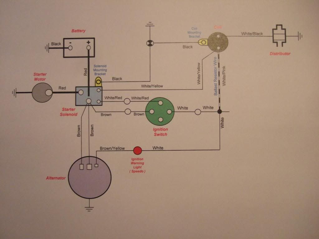
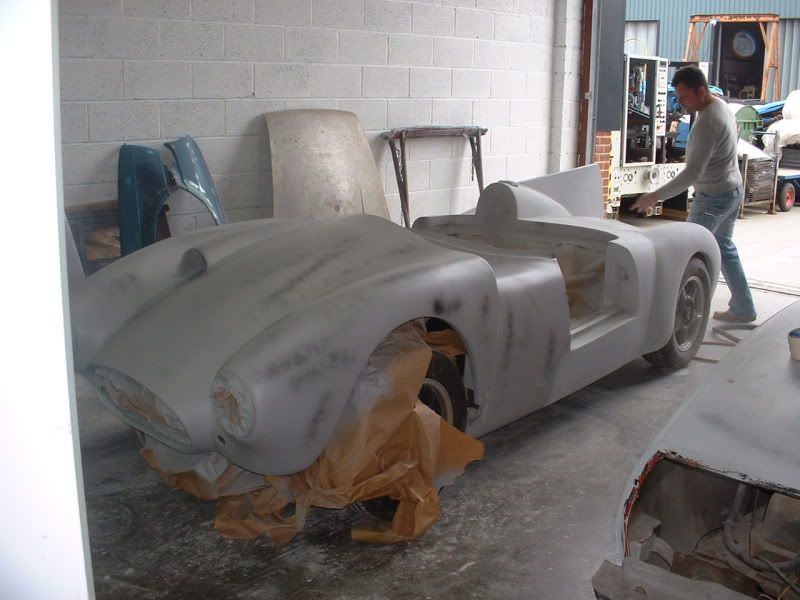
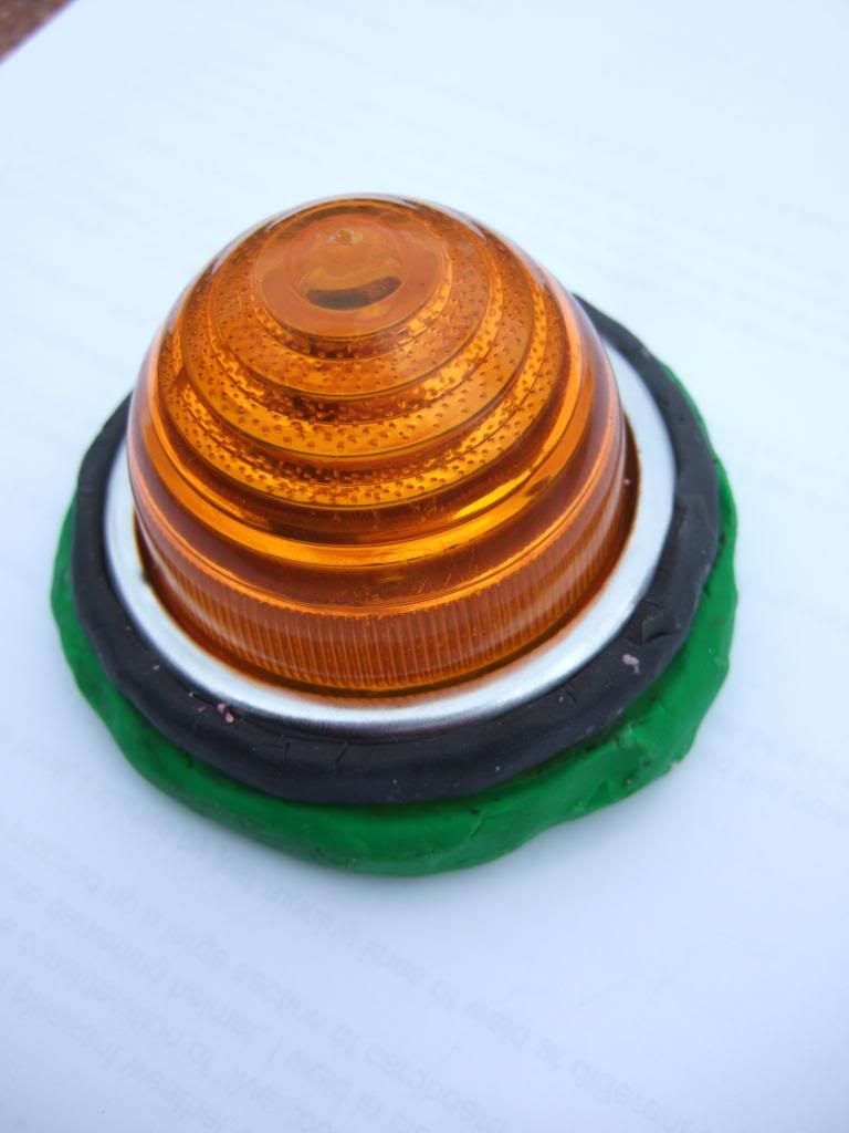
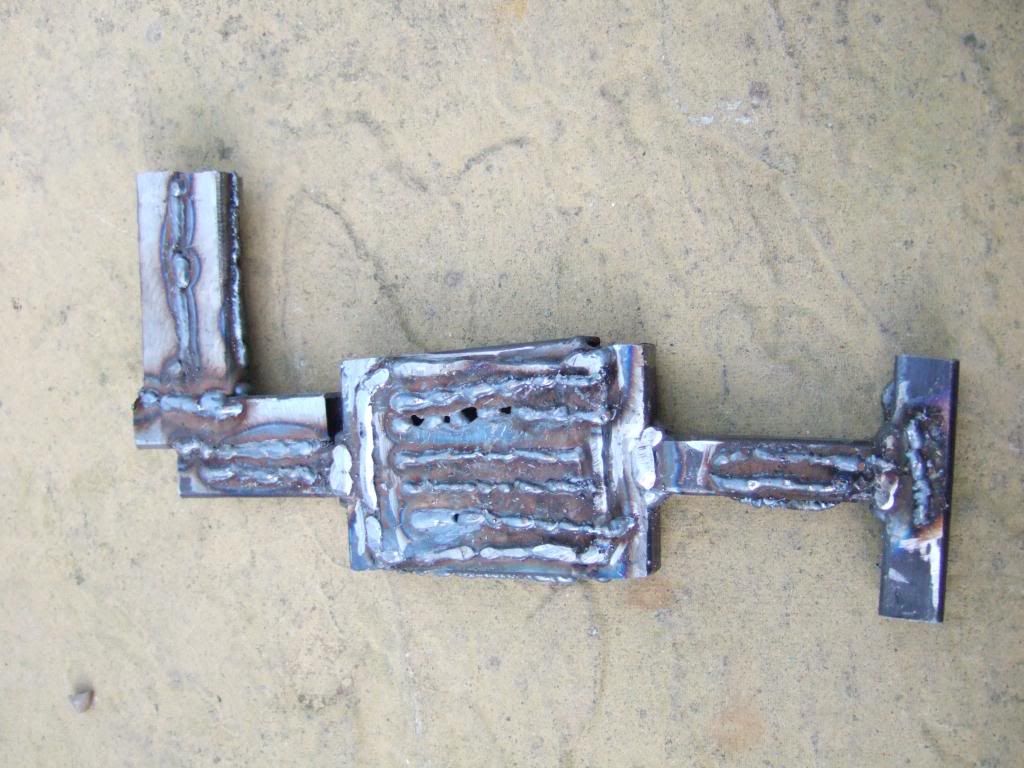
Which corresponds with the minimum number of connections I needed to make in practise, as seen here…

The coil mounting bracket is earthed separately as it is now attached to fibre glass & not metal as intended.
I've done the same thing to the Starter Solenoid, although not 100% sure it needs it, but it wont hurt to do it.
I intend to make just one more diagram covering everything else not shown above, or in my lighting diagram.
This will cover things like the fuel & temp. gauges, overdrive switch, car horns x2, etc.
I've actually found this a very useful exercise in expanding my understanding of how the car is wired up.
 Doors - The gift that keeps on giving...
I'm hoping
Mikmiglia will post some photos of how the doors on his
Speedster are set up / work.
As I'm sure that will be a big help in understanding how all the parts are meant to fit together.
I have resigned myself to a significant amount of work to make the best use of the original Cordite set up.
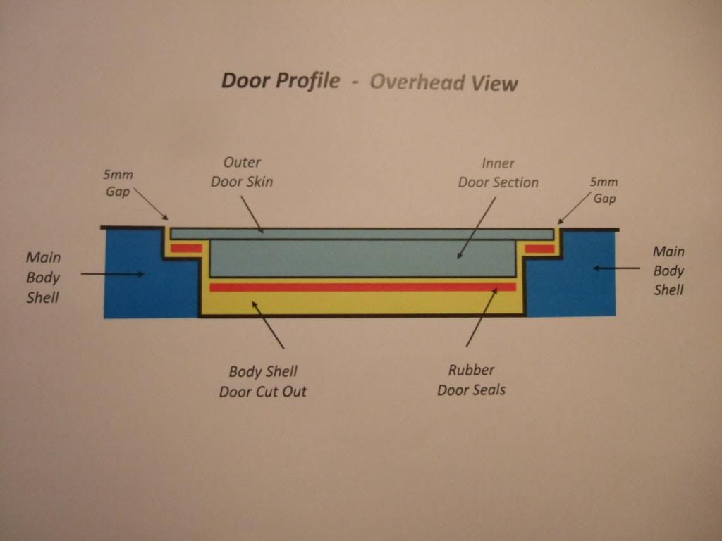
I think I will have to separate the inner door section from the outer skin and re-build everything from there.
I do not intend to change the initial curve from the outside of the body shell leading into the door cut section.
And it should be possible to make the outer door skin fit into this "hole" aiming for a 5mm gap all around.
Although, as previously mentioned, the door cut will need alterations so I can give the body a "shove" forward.
So I had another play on Power Point to see how some of the ideas in my head might work in practise.
Note: The sketches are not meant to be to scale & I've removed all the real curves as they are too hard to do!
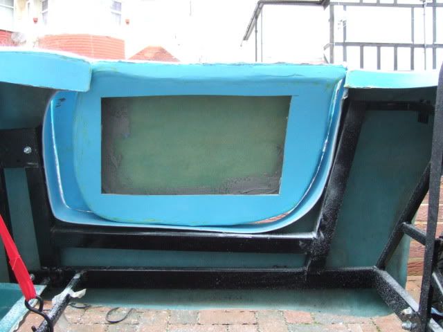
I want to go from my current set up of inner door section bearing no resemblance to the door cut out in some places…
To a situation where the inner door section evenly matches the door cut out all round (with curves in real life)…
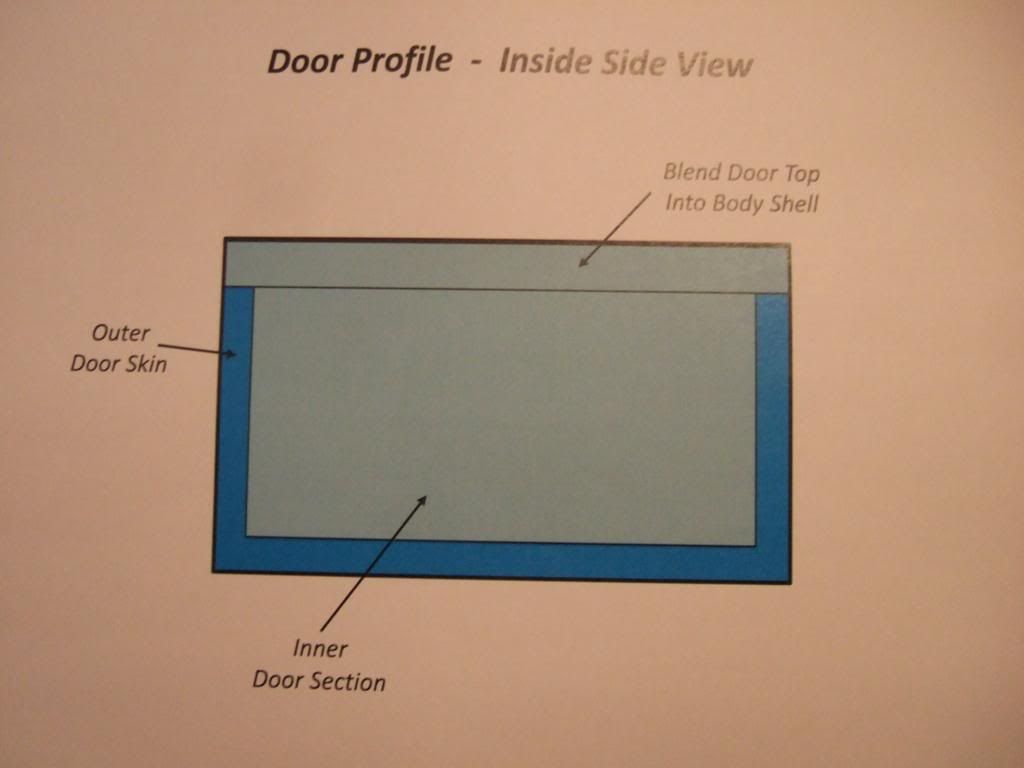
Similarly, I want the top of my doors to smoothly blend in with the rest of the body work. This is now…
And the inspiration for what a "blended in" door top could look like has been provided by
Mikmiglia…
So far, so good, but this work would effectively create a "lip" around three sides of the door "inner".
In which case, I'd expect to have a small "step" in the shape of the door cut for this "lip" to seal against.
Not sure what type of door seal to use, or how to attach it at this stage, but I am open to suggestions.
What do other builders intend to use as a seal on their bulk head for the bonnet to close against?
Anyway, I'll worry about the detail another day, this was my initial thoughts on sealing up the doors…
The current inner door section set up is significantly narrower than the width of the door cut out in the body.
It appeared that a "baton" had been used on a previous Sammio build for the door to close against…
( Note: That is what the long red line in the sketch above represents. )
But looking at this photo again, is the baton needed because there is no "step" built into the door cut out?
If there was a "step" on all three sides of the cut out, then the door would simply seal against that.
I included a baton (with seal in red) in this sketch, but have now decided that I don't actually need this….
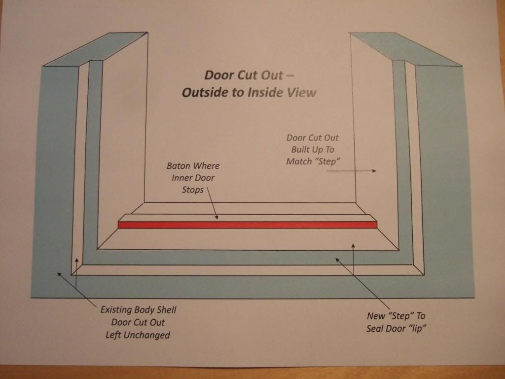
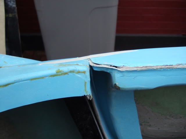
Don't get me wrong, building this "step" & matching the rest of door cut out to it is a major piece of work.
The only good news is that, as shown above, the first part of the step is the original shape of the car.
So if I can match both outer door skins to their respective cut outs*, they should look OK from the outside.
* The doors will stay as different sizes, there is already too much work needed without fixing this problem too!
Note: Matching doors will be available in the new Ribble kits, as my Cordite door design has been dropped.
Crikey, I'm worn out just describing all the work that lies ahead, and I haven't even started it yet!
Seat Belt Options - More Thoughts:
KISS principles do keep drawing me back to consider a
traditional "static" 3 point seat belt arrangement.
I think these would be easier to mount than building somewhere to mount a the retractor belt arrangement.
Mind you, if I am prepared to accept the restrictions of those, I might as well have the "looks" of a harness.
Saw these military harnesses on Ebay & they look the part, just not sure if they would be UK road legal?

Decisions, decisions, is it any wonder this build is going to take me forever and a day to complete!
Next steps:
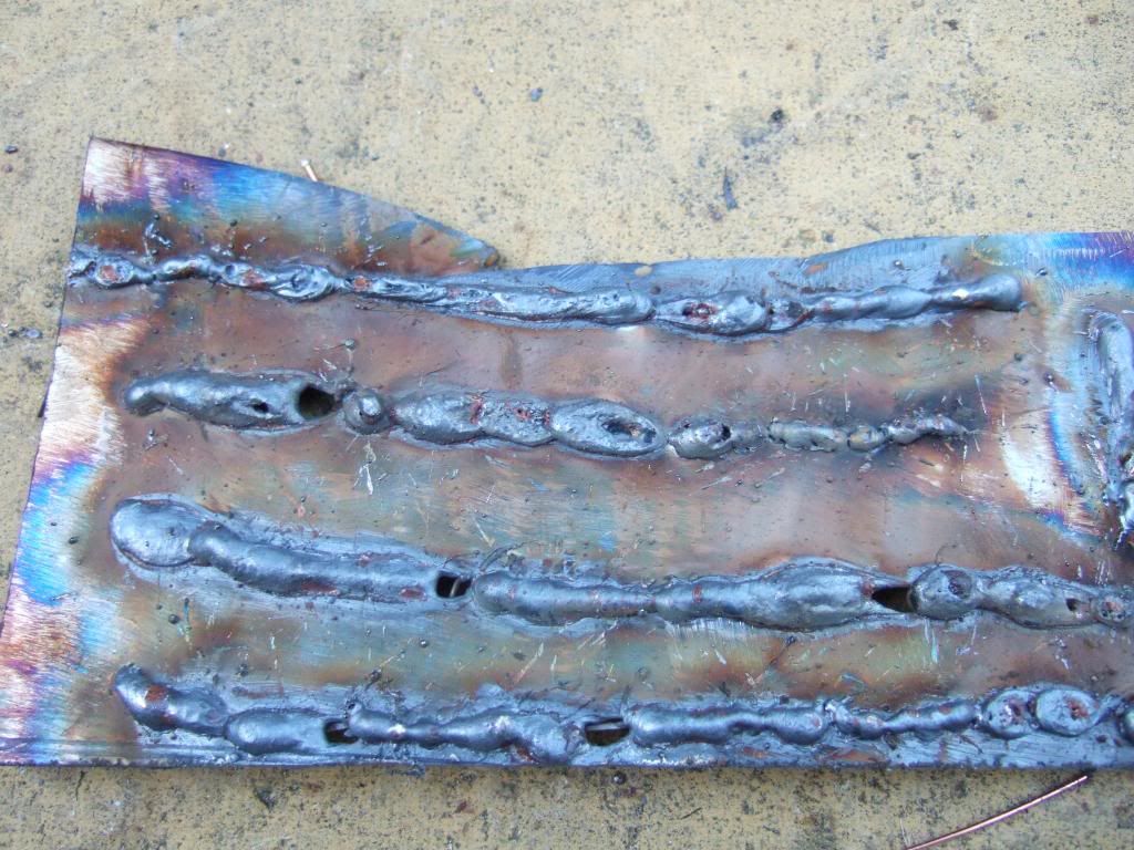
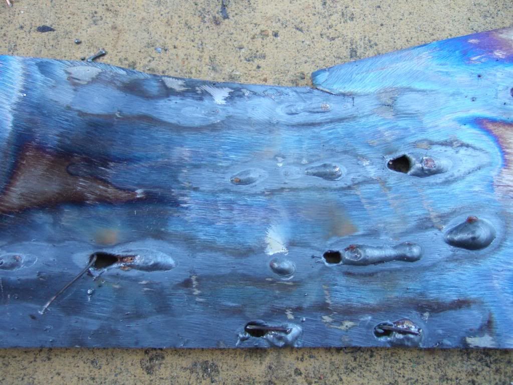
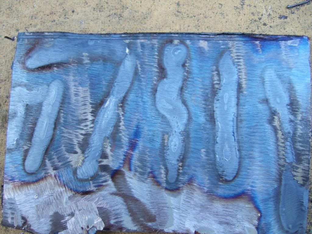
If the weekend weather holds, I hope to start work on my pedal mountings & get more welding practise in.
Until next time, take care, Paul.


 Linear Mode


