|
|
| Marlin 5exi builds Calling all you sexi builders....sorry 5exi builders, show us your progress. |

9th November 2010, 08:55
|
 |
Senior Member
|
|
Join Date: May 2009
Location: Hampshire
Posts: 147
|
|
 Module 3
I collected Module 3 from Marlin on saturday.
Went for the Door package, and the orange Gel coat in the end.
So onwards and upwards.
Any tips on working with GRP and fitting the fibreglass would be appreciated, although I think I have a good idea of what to do and how to do it.
Cheers
Steve
|
10th November 2010, 06:06
|
 |
Senior Member
Enthusiast
|
|
Join Date: Oct 2004
Location: Basildon, Essex
Posts: 1,800
|
|
Can't comment much on the bodywork as Marlin done mine.
But install the door popper buttons on the dash.
|
10th November 2010, 08:23
|
|
Senior Member
|
|
Join Date: May 2009
Location: Hampshire
Posts: 147
|
|
What do you mean by the door popper buttons?
The door release cable?
If you mean those wouldnt this be in the door itself? Unless the door lock is on the chassis and not on the door.
Cheers
Steve
|
10th November 2010, 13:20
|
|
Senior Member
Enthusiast
|
|
Join Date: Oct 2004
Location: Basildon, Essex
Posts: 1,800
|
|
Check your bit's but all I got from Marlin was the door striker bar on the for and the catch for the chassis. To get this to release, you need to release the catch on the chassis, opening the door.
I needed a solinoid (smooth handle kit) or i'v seen used, the central locking mechanism from the Rover donor. This then, on mine, through a relay with a button for the relay trigger.
|
10th November 2010, 14:14
|
|
Senior Member
|
|
Join Date: May 2009
Location: Hampshire
Posts: 147
|
|
I think i follow you
I dont have central locking and wont, dont even have locakable door catches.
I have a "Bonnect pull cable" and bear clwas as available from Car builder solutions
To get central locking to work i can see you need to be able to pull both door locks, so fitting the locks to the chassis makes sense.
I am considering fitting the door catches to the door, as per a normal standard design of car.
Only thing is you have reach in from the outside to open the door.
Cheers
Steve
|
11th November 2010, 07:37
|
|
Senior Member
Enthusiast
|
|
Join Date: Oct 2004
Location: Basildon, Essex
Posts: 1,800
|
|
Hi Steve.
Got no Internet connection at home at the minute. But what I'll do is take some pictures and draw a diagram to make a bit more sense.
|
12th November 2010, 14:33
|
|
Senior Member
|
|
Join Date: May 2009
Location: Hampshire
Posts: 147
|
|
Quote:
Originally Posted by limpabit

Hi Steve.
Got no Internet connection at home at the minute. But what I'll do is take some pictures and draw a diagram to make a bit more sense.
|
nice one, thank you very much |
13th November 2010, 10:17
|
|
Senior Member
|
|
Join Date: Oct 2008
Posts: 383
|
|
Hi Steve,
I think what limpabit is saying is (like the shelsley) you use the central locking solenoid to pull/push the lever in the door mechanism which then replaces the pull cable you normally have to open the door.
hth
Chris
|
13th November 2010, 16:35
|
 |
Senior Member
Enthusiast
|
|
Join Date: Nov 2007
Location: Somerset
Posts: 232
|
|
Body Building
I started fitting the body myself but ended up paying someone else to complete it. You almost have to assemble it off the car on a jig to mate up and fettle the joints then fit it to the chassis and adjust the position to fit the metalwork.
The first bits to fit are the dashboard and the arch behind the seats, fit this with tape to start with because you will not know how how it needs to be to start with. Remember the dashboard groove for the window screen may need to be trimmed and fettled to make the window screen fit properly with the best fit gap at the top to the top surround, I did that first then the body panels with the screen fitting to be done last job of all, perhaps even after IVA. Some kits need to raise the front of the dashboard by 12mm to reduce the gap at the top of the screen.
The side panels are next but don't fix them yet as you may have to move them forwards.
The front clam is key, it should not touch the window screen surround but should be fully supported by the two side panels and the hinge. The gap round the front edge with the outside of the window screen should be as small as practical but not touching or you will need rub pads on the touching parts. I fitted large dowels to the panels at the clasp points and holes in the clam to locate accurately when closed. (make sure the clasps are IVA proof, sprung retained racing type and with the option to fit a pin or lock)
To get the gap at the front I needed to take off 12mm at the joint between the side and the dashboard a bit of each so the panel was not too far forward.
Marks comment to me was if the joints are within 1/4inch its a good fit.
That's about right you can get it better but its very fiddly.
Dave Gallop got mine closer for me and the body shop are getting it nearer to a really good fit.
The rear clam is easy if you have got this far. The arch behind the seats is the key, once you have the clam lapped correctly over the lip and fully home forward, lock it down on the hinges. Then the arch can be fixed to match the height of the rear clam and the side panels.
I got it assembled and roughly fitted but with limited space in a single width garage I lost patience and figured I had better things to do with the time.
I wish you luck, I would rather remove and strip an engine from the crank up and refit the engine than fit the body work again, but that's a personal choice.
So basically nothing is fixed to a known point, everything moves to take up the slack and if you move one bit you may have to move everything along or up or down! You will end up with spare holes if your not careful.
You compromise in the end to make it look good and then remember is a kit car and all will be well and sanity will return, that's when I started spending the money on other people.
JohnC

|
15th November 2010, 14:48
|
|
Senior Member
Enthusiast
|
|
Join Date: Oct 2004
Location: Basildon, Essex
Posts: 1,800
|
|
Sorry Steve, been away all weekend and had no internet connection at home.
As John's post above, that's why I got Marlin to fit the bodywork, hood and windscreen & doors.
OK... the door "openers".
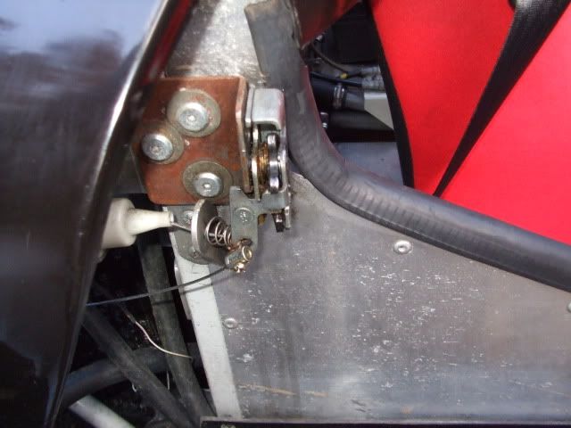
When I got my car back from Marlin (bodywork fitment etc), I had a catch attached to the chassis (with a make do cable for release) and a striker on the door:
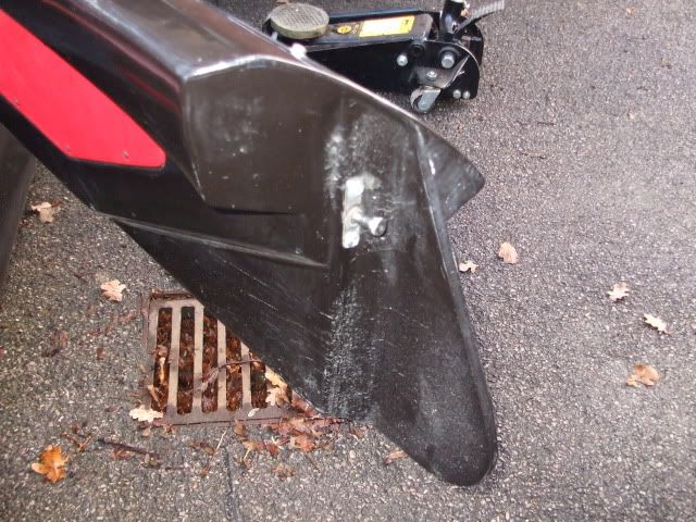
Striker on door:
Catch on chassis:
It was a start. But somehow, a way was needed to open the doors. On Marlins demonstrator at the time, they had a button behind the shoulders of both driver and passenger.
I used a starter button like this:
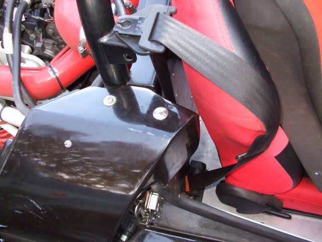

A bad position though. I will be moving mine to the dashboard area when convenient.
Then we needed a solenoid to release the catch on each door. I used something like this for each door and made the bracket in the photo.
http://cgi.ebay.co.uk/Boot-Release-D...item45f60f7425
Mine fitted:
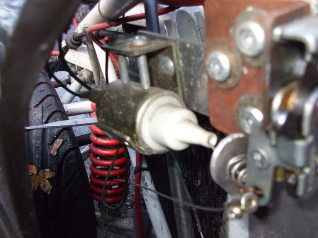
Now if you use a donor central locking (seen the Rover ones used), you get the release catch and solenoid in one unit 
Now the solenoid when operated, kept blowing the buttons. So needed to run it through relays. Again, I've seen the central locking ones used with these starter buttons, and not needing a relay.
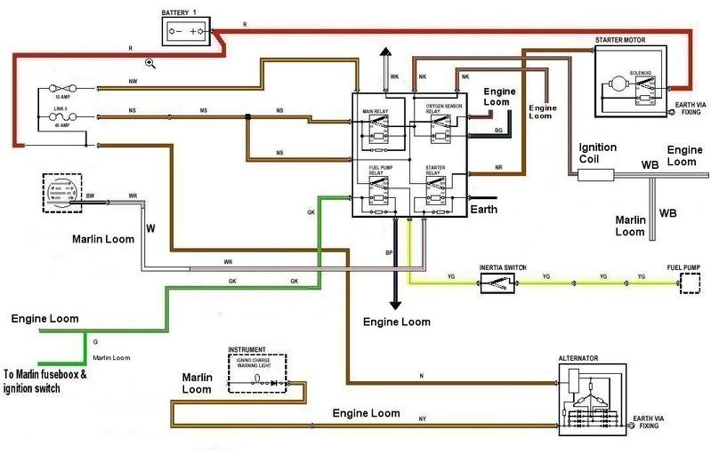
On the Rover, there are two 4 X relay boxes) in one unit. Either Starter relays or main beam etc. Looks like this:
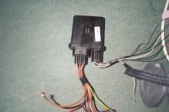
Here is the circuit diagram in use as a starter etc. I just used two relays, one for each door. Using the starter button as a relay trigger. 
Hope this all helps.
|
16th November 2010, 14:29
|
|
Senior Member
|
|
Join Date: May 2009
Location: Hampshire
Posts: 147
|
|
Fantasic,
thanks for the responses eea53, limpabit.
Ive fitted my aluminium side panles and offered up the GRP parts.
So far I have had to move my intercooler pipes (run around the outside) to the intercooler which is mounted at the front, I had to move them down so they fit in the width of the lower GRP side panels.
Im trying to figure out the impact of the roll bar and the bodywork, my first problem is does the roll bar need raising? At the front end does the first angle of the roll bar go level with the dashboard/windscreen groove?
Can anyone get a pitcure of this area? For me to get them to line up my roll bar is rasied 20mm,
also the rear end of the roll bar, how does the seat belt bar fit in? there is a bracket on the roll bar above the top of the rear bulkhead, but this isnt high enough to clear the GRP on the rear bulk head.
Can someone provide me with various photos of key areas of thier bodywork please....
if you cant get them hosted for viewing,
Email them to me, steve at stsa.co.uk
Many thanks
Steve
|
16th November 2010, 19:25
|
|
Senior Member
Enthusiast
|
|
Join Date: Oct 2004
Location: Basildon, Essex
Posts: 1,800
|
|
If you are using standard seatbelt, you just bolt in 3 places. On the roll bar as in picture above. Then bolt on two places on the chassis. Holes are already there and tapped.
You will need a long seatbelts beleive it or not. Like these.
http://www.cbsonline.co.uk/other-seat-belts-213-c.asp
You only need the bar for harnesses. |
16th November 2010, 20:01
|
|
Senior Member
|
|
Join Date: May 2009
Location: Hampshire
Posts: 147
|
|
I was going to go for a 4 point harness,
and wasn't sure how the bar fits in given the GRP on the rear section.
|
16th November 2010, 21:16
|
 |
Senior Member
Enthusiast
|
|
Join Date: Jul 2005
Location: Dorset
Posts: 1,180
|
|
The 4 point harness bar bolts between the right-angled brackets on the vertical sections of the rear hoop. You use the unused bolt hole visible in the fourth picture above posted by Limpabit.
My memory is that the stock Marlin bar isn't liked by SVA / IVA inspectors, as it isn't very stiff.
Likewise, my inspector said had I not reinforced the standard right-angle bracket (fitted with an inertia reel), he would have failed my car.
|
17th November 2010, 07:07
|
|
Senior Member
|
|
Join Date: May 2009
Location: Hampshire
Posts: 147
|
|
Understand you there,
the right andlged bracket has two holes one on the top and one on the side
If the bar is mounted on the holes on the side does yours interfer with the GRP on the rear bulkhead?? Have you had to modify it? Or does it have clear line of sight between the two?
Or does it mounted on the top holes somehow?
Soo many questions...........
Cheers
Steve
|
17th November 2010, 07:52
|
|
Senior Member
|
|
Join Date: May 2009
Location: Hampshire
Posts: 147
|
|
Thinking about what you said,
I may end up cutting of the supplied angle brackets for the seat belt bar.
Getting some tube the same as the roll cage,
weld it in slightly higher to clear the top of the GRP.
That should satisfy IVA, and also provide increase strength in the roll cage.
hmmmmmm
never easy |
17th November 2010, 10:42
|
|
Senior Member
Enthusiast
|
|
Join Date: Oct 2004
Location: Basildon, Essex
Posts: 1,800
|
|
Or fit seatbelts for now, pass IVA, then do the harness project.
|
18th November 2010, 08:52
|
|
Senior Member
|
|
Join Date: May 2009
Location: Hampshire
Posts: 147
|
|
Will do the harness project now,
dont want to buy seat belts only to buy some more later.
|
18th November 2010, 08:54
|
|
Senior Member
|
|
Join Date: May 2009
Location: Hampshire
Posts: 147
|
|
Can you anyone provide me with some photos, of the front roll cage , dashboard and windscreen?
Hust a photo of where the roll cage "angle" is in relation to the other 3 components I have mentioned
Last edited by nutter; 18th November 2010 at 08:59..
|
19th November 2010, 08:09
|
|
Senior Member
Enthusiast
|
|
Join Date: Oct 2004
Location: Basildon, Essex
Posts: 1,800
|
|
When Marlin fitted mine, the raised the dash board by I would say 10-15mm with spacers. If you look at the picture below, you can see the two screws holding the dashboard. Far right near boost gauge and and left of the dashboard near rubber mat.
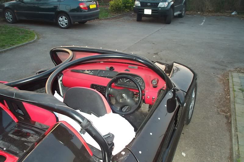
Here are some photos from different angles.
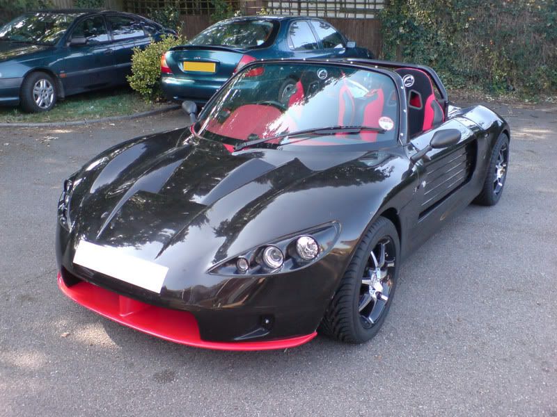
Let me know if you want more photos. Might be better to come and have a look. |
|
Currently Active Users Viewing This Thread: 1 (0 members and 1 guests)
|
|
|
 Posting Rules
|
You may not post new threads
You may not post replies
You may not post attachments
You may not edit your posts
HTML code is Off
|
|
|
All times are GMT +0. The time now is 14:57.
|


 Linear Mode

