|
|
| Sammio Builds and discussions Sammio bodied car builds and specials |

3rd July 2014, 19:52
|
|
Senior Member
|
|
Join Date: Apr 2012
Posts: 1,163
|
|
Bit late now Paul but if you have any voids left that need filling like you did on the scuttle you can use foam available from the likes of East Coast fibreglass, filling the gap with something solid wont necessarily add the strength you expect and sometimes adding a layer of foam actually adds strength by separating the laminates and making them work against each other to increase rigidity.
Our race car has floors made of a carbon foam Kevlar material we made ourselves quick clip here of our first sample:
https://picasaweb.google.com/1115295...80740646437682
PS should be swinging by the bodyshop supplies place tomorrow afternoon
Mac |
4th July 2014, 07:11
|
 |
Senior Member
|
|
Join Date: Feb 2012
Location: Wembley, London
Posts: 5,056
|
|

Mac - I know I am making this up as I go along, so your feedback is always welcome. 
This was my original thinking, so please correct me if I have made a complete mess of it.
- There is a "base" layer of multiple sheets of CSM that sits on the Spitfire bulkhead.
( From cockpit edge to bonnet lip. )
- Eventually there will be a "top" layer of multiple sheets of CSM.
( Again, stretching from cockpit edge to bonnet lip. )
- In some areas these two layers are separated by some "filling".
( The cable trunking & a mixture of home made & standard fibreglass filler. )
- But in the majority of the scuttle the two layers effectively form a single, extra "thick", layer.
- I had hoped the strength would come from the fibreglass layers, regardless of the "filling" I used in between.
The only other thing that I hoped would work in my favour is the Spitfire bulkhead itself.
There will be a large surface area for the bonding paste, which I hope reduces stress on the scuttle. 
Well that was my theory anyway, but I'd rather know I needed to do more work now, rather than later.
Thanks, Paul. 

|
4th July 2014, 07:22
|
|
Senior Member
|
|
Join Date: Apr 2012
Posts: 1,163
|
|
Paul, nothing wrong with the way your doing except your adding weight but I'm guessing that's not a priority. The only reason I mentioned the foam is that it would have been a bit quicker and less messy than filling the void with offcut filler.
Keep up the good work.
Mac
|
4th July 2014, 21:01
|
|
Senior Member
|
|
Join Date: Feb 2012
Location: Wembley, London
Posts: 5,056
|
|
Quote:
Originally Posted by Viatron

... it would have been a bit quicker and less messy than filling the void with offcut filler...
|
:lightbulb:
Mac - Sorry mate, I now understand what you mean, the foam is an alternative to the filler.
I thought I was causing a problem to the strength of the fibreglass by using the filler. 
- - - - - - - - - - - - - - - - - - - - - - - - - - - - - - -
A Tough Day - Part 1:
This turned into one of those days where I seemed to be walking up the down escalator.
So despite making some progress in some areas, the end of this project seems further away than ever. 
It started well enough as I cut out the next sections of fibreglass matting for the scuttle.
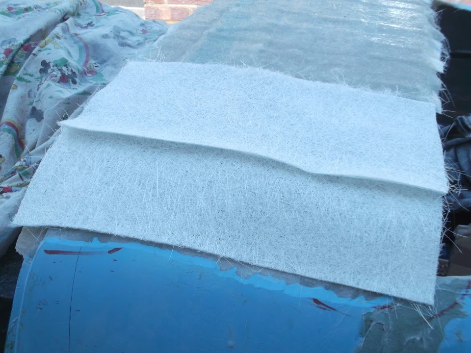

They went on with no problems.
Although there is still a bit of work to do before I have smooth curves at either end.

Having said that, the driver's side is a lot closer than the passenger side at this stage.
- - - - - - - - - - - - - - - - - - - - - - - - - - - - - - -
Then I had another look at the options for positioning the side repeaters.
This is linked to the work required to create a seal between the bulkhead and the body shell.
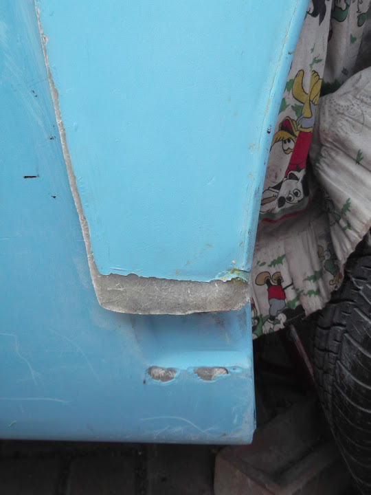
I can't use a simple panel like Mr T's.
Because the bottom of my bulkhead looks like this.

So I will need to seal along the bottom edge here.

Then work upwards around here.

Note: You can see the two holes where the VIN plate will be mounted.
Finally the seal will end in line with the top part of the bulkhead here.

The obvious place for the side repeater would be on the cockpit side of this seal.
But that space will be required for mounting the side mirrors.
The alternative is somewhere on the engine bay side of the seal.

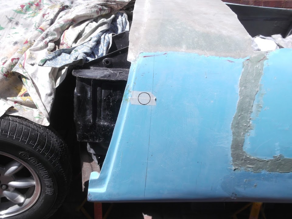
There is plenty of room for the back of the light to fit.

Although I would need to protect the wires from the elements.
End of Part 1...
|
4th July 2014, 21:01
|
|
Senior Member
|
|
Join Date: Feb 2012
Location: Wembley, London
Posts: 5,056
|
|
A Tough Day - Part 2:
Before making a final decision I decided to do some testing with a scrap section of fibreglass.
The good news is I finally found something my cheap hole saw set can cut through.

The bad news, is the hole isn't quite big enough for the side repeater to fit.

Still, a bit of work with a hand file later and it was in.

Although I couldn't get it to "click" into place until I'd thinned the back of the fibreglass a bit.
( Not easy to see in the photo. )

It was only after doing all this work I went to check the position on the driver's side.
Which lead me to my first sense of humour failure of the day.
The reason the side repeater works well on the passenger side is that it is longer than the driver's side. 
Options:
- Let the side repeater highlight the differences between the edge of the Spitfire bulkhead and the edge of the body shell.
- Move them to the cockpit side of the "seal", but they did look a bit odd that far back.
- Fit them to the bonnet (like TlrTone) and re-work all the wiring to match.
- Do not fit side repeaters at all, as let's face it, they are an optional extra.
If I stick to a KISS approach, then the way forward is the last option.
So the decision is made, no side repeaters for me.
I will add them to the list of things I must get round to selling on Ebay one of these days.
Whilst I have added extra connections for these lights to my wiring loom, it will be easy to wrap them up.
- - - - - - - - - - - - - - - - - - - - - - - - - - - - - - -
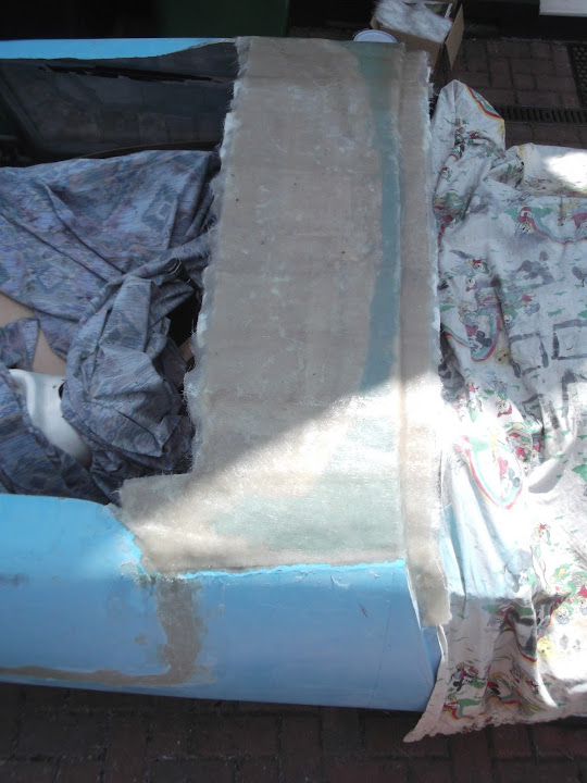
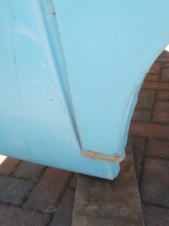
Eventually the scuttle was set hard enough for me to give the edges a quick trim.

As before, this is just to avoid splinters, not the final shape of the lines.
Then I carefully removed the body shell, so I could sand the filler on the bulkhead.
This makes it a little easier to see the curves of scuttle.


Although the sloping drive isn't helping the angles in the photo much.
- - - - - - - - - - - - - - - - - - - - - - - - - - - - - - -
After a rough sanding of the filler, & some etch primer, the two flattened lumps looked like this.


I had also added some filler to the ends of the bulkhead that I'd "trimmed".


Plus the surplus hole in the bulkhead.

- - - - - - - - - - - - - - - - - - - - - - - - - - - - - - -
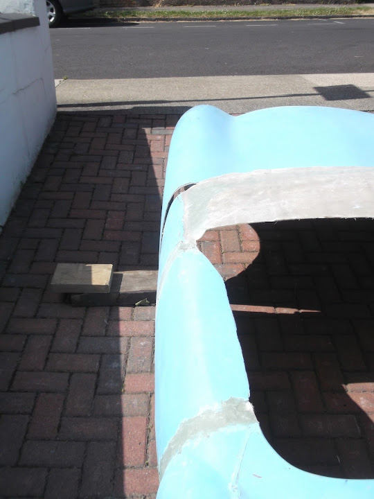
While the body shell was on the drive, I offered up the bonnet to it to see what I was up against.

The first issue is the bonnet is supplied "over size" to allow the back edge to be trimmed to fit.
So it will not sit in place at the bottom like this.

On the other side it is not clear if the bottom edge of the bonnet should be where the gel coat ends, or where the fibreglass does.
In which case, that would need to be sorted before the back edge was cut.
I also needed to prop the bottom edges of the bonnet inwards as they were wider than the bodyshell.

This is something I know I have seen Mr T fix on his bonnet.
End of Part 2...
|
4th July 2014, 21:02
|
|
Senior Member
|
|
Join Date: Feb 2012
Location: Wembley, London
Posts: 5,056
|
|
A Tough Day - Part 3:
With the bonnet as close as I could get it to fitting, I could have a look at what I was up against.
The good news is that the edges of the bonnet are vaguely in line with the body shell looking forwards & backwards.


Obviously, I knew that the top edge was going to need some work.

So the whole rear bonnet line needs to be raised to match the new shape of the body shell.
Without wishing to underestimate how much work that involves, this does seem possible following the work Micky1Mo did.
However, my real frustration stems from the fact I can't really line anything up until the body shell and bonnet are fitted to the car.
As the position of the bonnet hinge will determine where, and how, the bonnet actually reaches the body shell.
But I can't work out where the bonnet will go because the Spitfire bonnet brackets are in the way.
When after two years of these brackets being in the way the "camel's back" was finally broken today.
But before I cover want happened next, I need to go back a bit first...
- - - - - - - - - - - - - - - - - - - - - - - - - - - - - - -
Recently I sent yet another letter to the DVLA asking for confirmation that the Spitfire bonnet brackets are officially "brackets".
Which means they can be removed and I would still have an "unmodified chassis" under the re-body rules.
This included this photo of a restored chassis that AndyP57 posted the other day.

Plus this print out from Rimmer Bros. that I added some colour to in order to highlight the issue.

My argument was the chassis remained the same throughout the Spitfire range, but different brackets were used for different models.
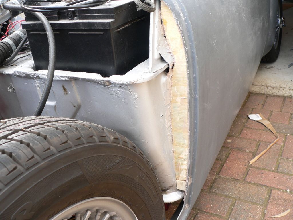
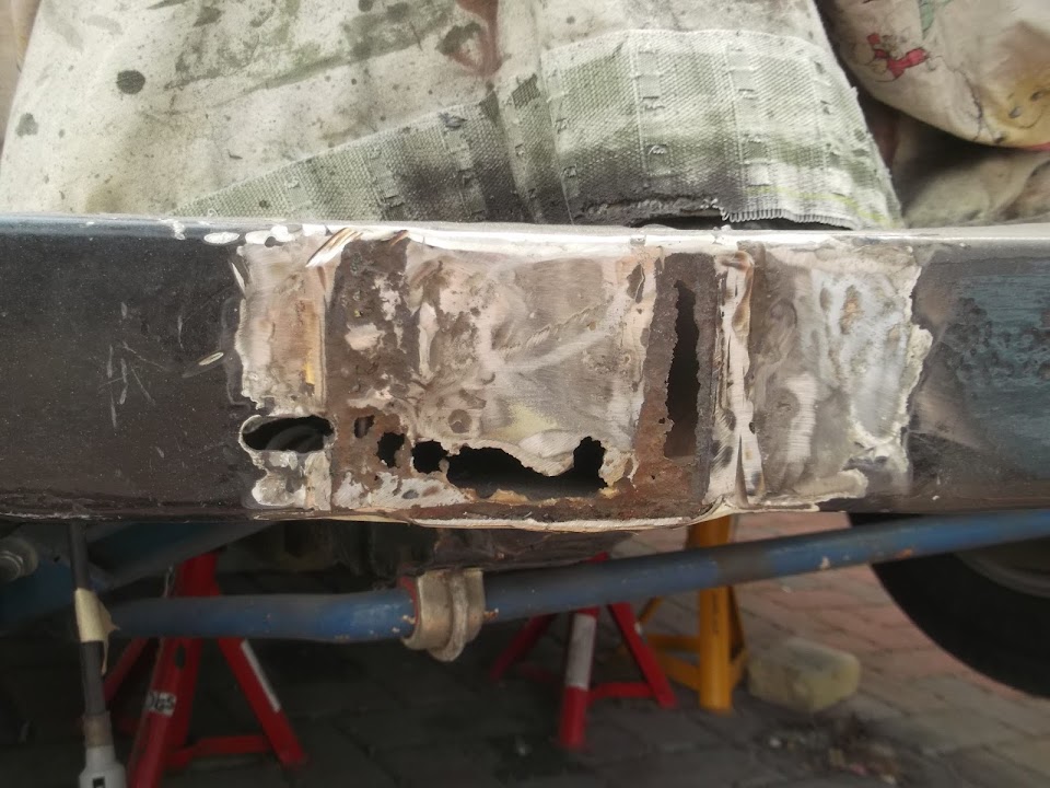
Well today I finally put my money where my mouth was and attacked the brackets with my angle grinder. 
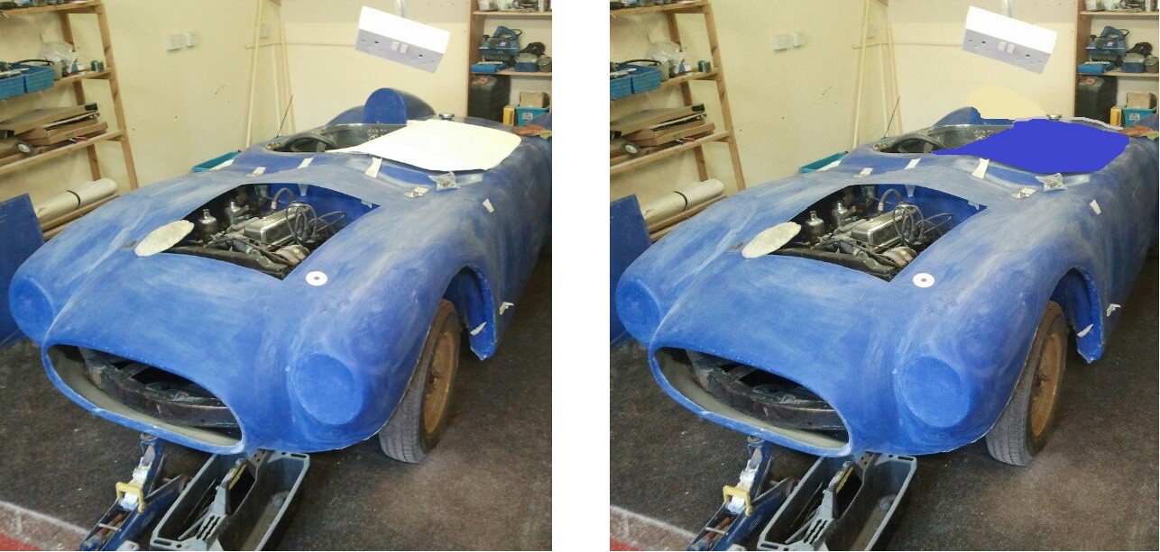
Before:

After:
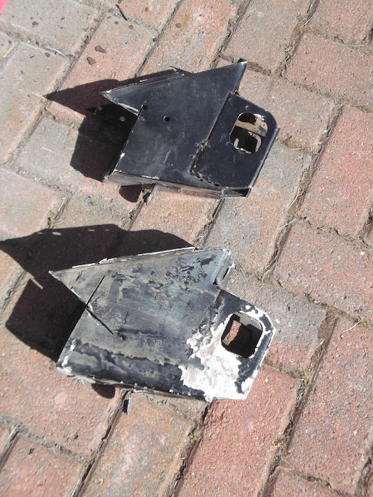
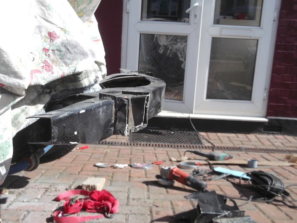
I deliberately left the "rump" that you can still see so that I can come back and trim this off with more care another day.
( Plus the fact that my angle grinder gave up the ghost shortly after this, due to a problem with the cable. )
On first inspection, a pile of rust and a lump of filler were not good omens.
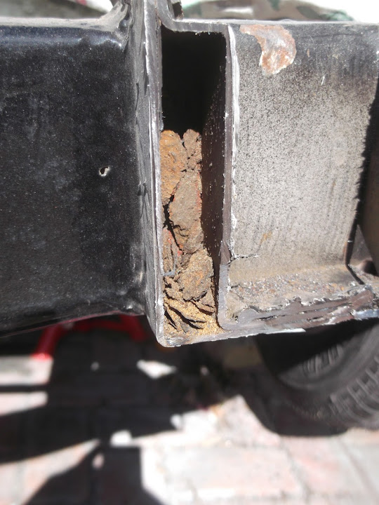

So it was no surprise to find rust on the chassis hiding behind the bracket. 


Whilst trying to look on the bright side, at least I know how to repair the damage and make good the chassis.
Plus it doesn't seem right to be building a Sammio without spending some time patching the chassis like everyone else. 
Normally I am not a gambling man and I always intended to wait until the re-body inspection before removing these brackets.
But the Rimmer Bros. diagram has convinced me I have a water tight case in support of an unmodified chassis.
To be honest, compared to the final part of this update, this is the least of my worries at the moment.
End of Part 3...
|
4th July 2014, 21:03
|
|
Senior Member
|
|
Join Date: Feb 2012
Location: Wembley, London
Posts: 5,056
|
|
A Tough Day - Part 4:
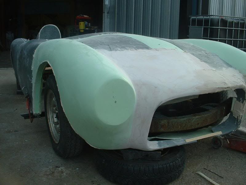
I started packing up for the day by putting the body shell back on.
Then with the brackets out of the way, I could finally see how close I could get the bonnet.

Obviously this doesn't look right at all, but remember the car is sitting on jacks, so the front wheel has dropped.
In addition the bonnet is pivoting across the top of the radiator which is pointing the back upwards.
But the real issue is where the bonnet is relative to the front cross member.

Forget the fact that the bonnet is slightly wonky, that is just how the tie down straps are working.
The key is the fact that my bonnet already had "factory" hinges fitted in the middle of the opening like so.
( So I am trying to line up these brackets with the chassis cross member. )

Now I have gone back through a number of old threads to find any clue as to how the bonnet should be fitted.
If I look at AndyP57's first Cordite/Navigator demonstrator I can find this "hump / no hump" mock up.
The point to note is that the chassis cross member is at the bottom of the bonnet opening.
( If anything, the chassis appears to sit below the opening. )
When the same car appeared at Stoneleigh the bonnet had been fixed into position.
However, you can clearly see the chassis cross member sitting at the bottom of the bonnet opening.
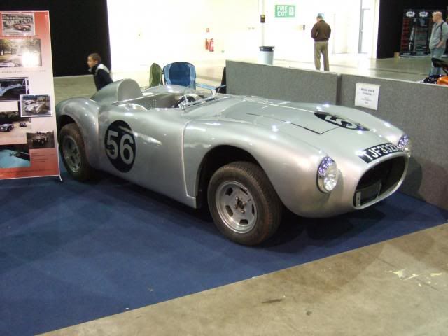
Here is a photo of the original Sammio Cordite, although I never saw a photo with the bonnet open.

I guess I am only just spotting how high the bottom of the bonnet opening is off the ground.
However, this was that car under construction.
Again, there is a recurring theme that the chassis cross member is at the bottom of the opening.
Finally, we have the red Ribble "Turnkey" Navigator which has the hinge bracket on the chassis like so.
( Which is where I was expecting to fit mine. )

However, you can just about see that the bonnet bracket is at the base of the opening.

I must confess that my head is hurting (again ), but here is what I now think.
The good news.
- The bonnet will clear the radiator with ease, as the front of the bonnet needs to be raised higher.
- Despite my bonnet hinges being in the middle of the opening I think I can work around that.
The bad news.
- The front of the car sits much higher than I was expecting.
- My wheels will be "lost" in the front arches.
( Note: I am NOT going to buy bigger wheels and tyres. )
I know I can re-work/extend the arches to narrow the gap above the wheels, but it is yet more work.
I will have a closer look at all this another day as I was fed up with the whole thing when I finished today.
Please forgive all the words and photos in this post, but it is a big help to me to write all this stuff down.
Then I can come back to it and have another think about what to do next.
Also, I think I might have been out in the sun too much recently as the problems are slowing grinding me down.
So I will end on a positive note that if I look back I know I have made really good progress on this build.
Especially given the facts that I'm building outdoors, learning new skills & the challenges this particular kit has presented.
I will try to stick to my "chipping away" approach and see where that gets me.
Until next time, take care, Paul.
Last edited by Paul L; 5th July 2014 at 08:33..
|
7th July 2014, 16:10
|
|
Senior Member
|
|
Join Date: Feb 2012
Location: Wembley, London
Posts: 5,056
|
|
Weekend:
I gave myself a complete break from car work over the weekend to re-charge my enthusiasm.
As I must confess that I was pretty fed up with the whole project after Friday's big session.
Although I did go back through some of this build thread to remind myself of recent progress.
As I looked back, I also gathered some rather nerdy build statistics:
- 25/Oct/13 was the day I started repairing the Spitfire bulkhead in my back garden.
- 253 days have passed from that point to my last session on the car on 4/Jul/14.
- I have done some car related work on 191 of those 253 days, which is a pretty good effort really.
- The time spent per day has ranged from just a few minutes at worst, to full days at best.
- Photos of big puddles in my garden also reminded me that rain remains my biggest enemy.
So whilst there is no denying the amount of work that lies ahead, I will continue to chip away at it.
- - - - - - - - - - - - - - - - - - - - - - - - - - - - - - -
Mac's Navigator:
The timing of this build is also a big help in terms of my motivation too.
No doubt you will have seen the great "step by step" guide to bonnet trimming here:
http://www.madabout-kitcars.com/foru...&postcount=532
This post also confirms that the bonnet needs work to sort out the wheel arches.
But I'm really looking forward to seeing how he sorts out the bonnet hinge arrangement.
I spoke to Mac on the phone today and will be posting some stuff about my own bonnet later.
- - - - - - - - - - - - - - - - - - - - - - - - - - - - - - -
Rain Stopped Play:
I did manage to get a little bit done today, before the heavens opened up on me.
I started by cutting out a section of wiring from my angle grinder that had frayed internally & re-joining it.
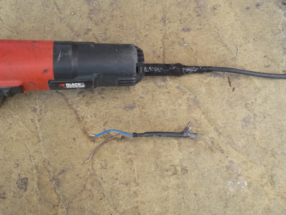
Then it was given a good test of cutting and grinding as I removed the Spitfire bonnet bracket "stumps"


The next job will be to cut out and repair the rusty sections of the chassis.

I also did a lot of checking the bonnet, which will be covered in the next post.
( Due to the limits on the number of photos per post. )
But in order to take the final photos I wanted to get the car off the jacks and onto the ground.
One of the biggest problems with jacking the car up on a sloping drive is it wants to "slide down the hill".
So I had to put some serious effort into pushing the car back up the slope while it rested on the trolley jack.
DO NOT TRY THIS AT HOME!
The good news is that I finally got the car in the position I wanted with the wheels back on the ground.
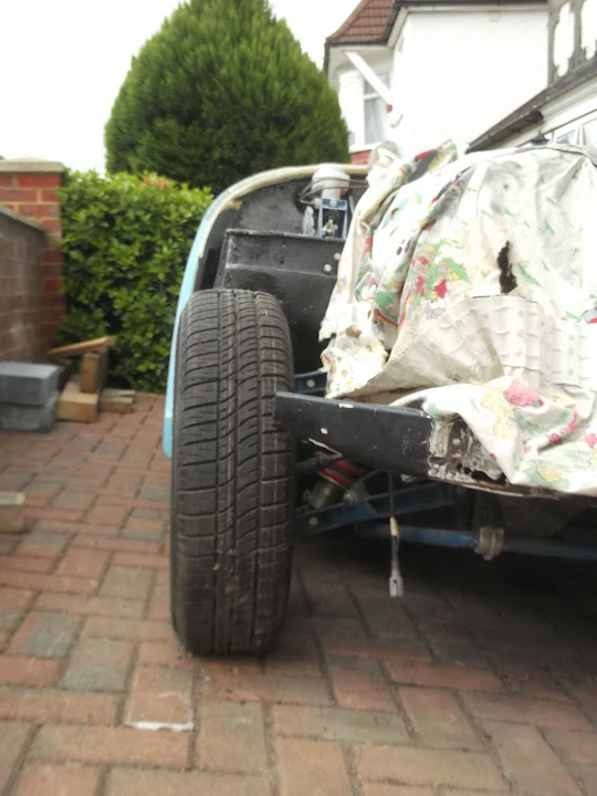
Although the slope does "tuck" the passenger side in.

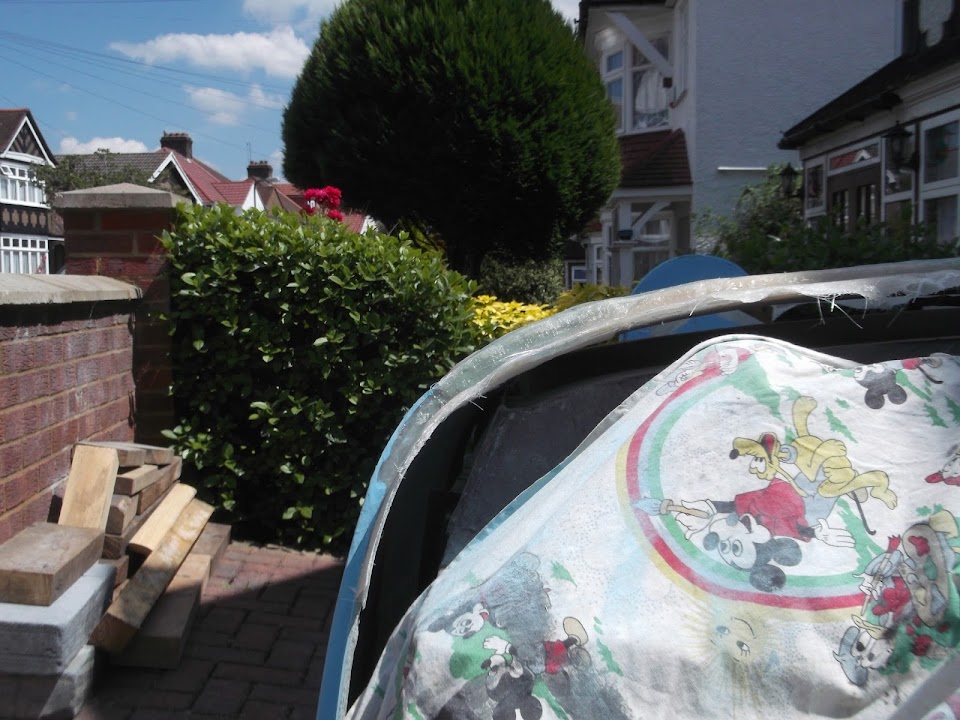
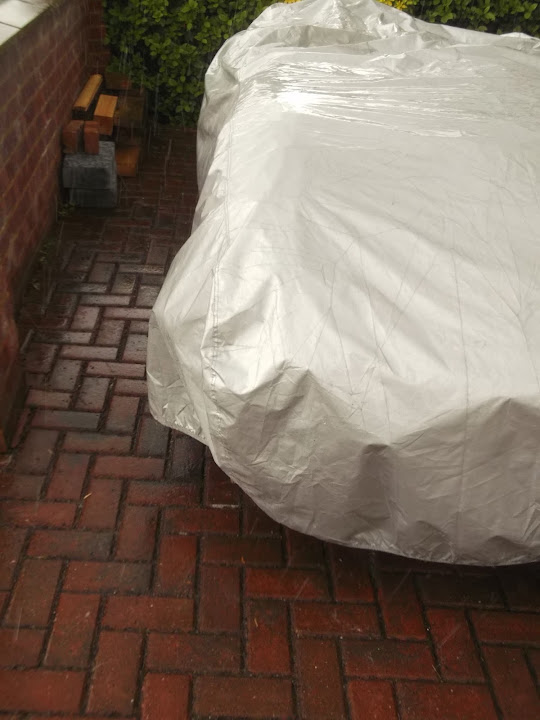
The bad news is that by now the sky looked like this and my time outside was doomed.

The really bad news is that I had not finished packing up by the time it started bucketing down.
So by the time I finally got the cover on I was a drowned rat.
At least I had made a return to the build process, back to ticking off the jobs, one at a time.
Cheers, Paul.
|
7th July 2014, 16:12
|
|
Senior Member
|
|
Join Date: Feb 2012
Location: Wembley, London
Posts: 5,056
|
|
Bonnet Check Up:
This is my rough guide to the Cordite bonnet so that Mac can see if my issues match his.
I started by trying to line up the bottom edges of the bonnet with the body shell.

Although the curves in the bonnet, compared to my plain scuttle, stop me getting it any lower at the bottom.

In addition, the fact the car is on jacks makes it harder to see how the wheels would fill the arches.


I managed to find enough bits of wood to hold the bonnet in roughly the right place.

Which is clearly much higher than it was during my previous attempt at test fitting.
Looking at the gap between the headlight mounting section & the bonnet "nose" there are differences.


The angle and length of the nose is also different on both sides.
( I used the holes drilled at "9 O'Clock" as my guide. )

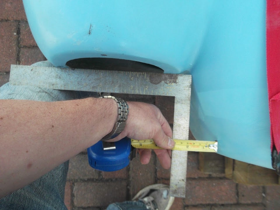
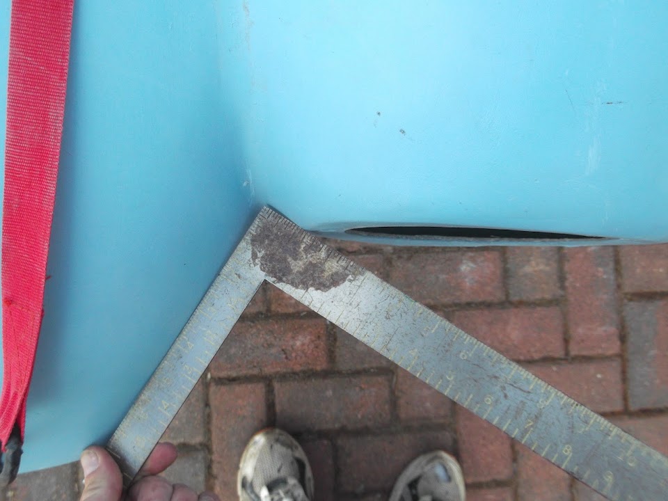

Obviously holding a set square in place with my leg for the photo is not exactly precise, but you get the idea.
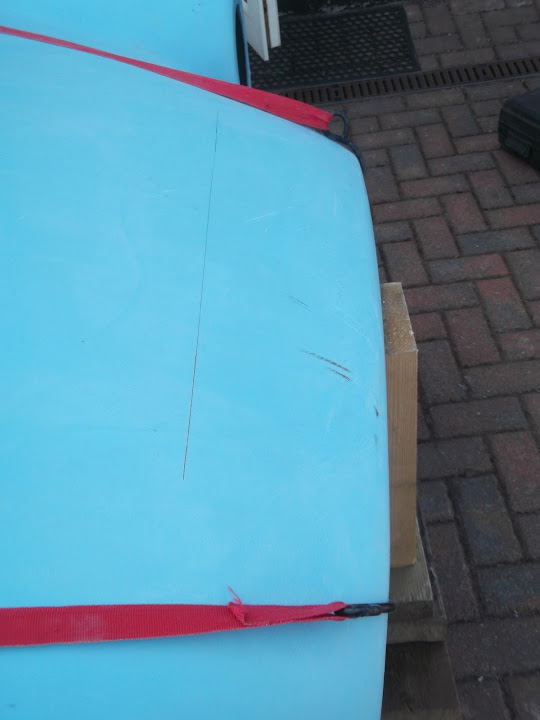
I marked out roughly where the two headlight mounts were across the bonnet.
( The wood/line were straighter than they might look in the photo. )

Although the line isn't very clear, the passenger side of the nose is longer than the driver's side.

OK, technically, it could be the headlight mountings that are forwards / backwards.
I am sure Mac's measurements will be a little more technical than mine.
But it was never a good idea to bring any kind of measuring devices any where near this project.
I will take a few more photos with the wheels back on the ground during my next session outside.
( Which will not me any time soon, given how hard it is raining as I type this up! )
So until next time, take care, Paul.
|
7th July 2014, 19:30
|
|
Senior Member
|
|
Join Date: Apr 2012
Posts: 113
|
|
Hello Paul,
Nice to see you like my car with the brookland screens.
These screens have only one problem;you're blown away because of the wind is going under them!
I,m thinking of a construction to deflect the wind over the
screens.
https://mail.google.com/mail/u/0/?ui...331809992-1&zw
In the stage ýou're in you could shape the scuttle to deflecte the wind.
Keep up the good work,Rob |
8th July 2014, 12:59
|
|
Senior Member
|
|
Join Date: Feb 2012
Location: Wembley, London
Posts: 5,056
|
|
Jerome - Thanks for the feedback Rob.
Although I couldn't seem to get your link to work.
I actually started looking at how a deflector for the aero screens might work today.
( See 2nd post below. )
- - - - - - - - - - - - - - - - - - - - - - - - - - - - - - -
More Bonnet Photos:
After yesterday's wash out, I took advantage of some morning sunshine to test fit the bonnet again.
As one of the issues that Mac mentioned was one wheel arch not covering the tyre.
So this is the view from above...
Driver's side:

Passenger side:

And, if anything, the passenger wheel is being pushed out at the top like this.
Although it is my passenger side rear wheel which sticks out the most.

Unfortunately, that was the side that Mac did a major "cut & shut" to make the new Navigator buck.
The other issue with the bonnet, is how it will tilt forward around the chassis.
Up until now, I've been unable to really look at this, as the Spitfire bonnet brackets were in the way.
Now I am able to check it, I wish I'd left the brackets on for a while longer.
The first problem is that the ends of the front cross member prevent the bonnet sitting further back.

If you look at the photo of the red Navigator I posted on Friday, the ends of the chassis have been cut off.
However, that red car was for export and there is no way I can touch this in the UK before a re-body inspection.
In addition, the area below the bonnet nose opening will foul the chassis if the bonnet tips.


So I just left the bonnet propped up in an open position and at this point things are looking promising.

Until you then see where the bonnet hinges are in relation to the chassis...

If I lower the bonnet a bit more, I can "push it in a bit", but it is not much better.

This is the reason I am looking forward to seeing how Mac makes this work, as my head hurts just thinking about it.
So far, Micky1Mo's hybrid is the only Cordite/Navigator I've seen a photo of with the bonnet open.

Looking at his build thread again, it looks like his bonnet sits a bit lower, relative to the chassis cross member, and further forward.

Finally, as I can't drop the bonnet due to the new scuttle profile, I now have a "Gasser".

At least this gives me plenty of clearance under the bonnet.

End of Part 1...
|
8th July 2014, 12:59
|
|
Senior Member
|
|
Join Date: Feb 2012
Location: Wembley, London
Posts: 5,056
|
|
More Mocking Up Work:
Whilst I don't need to sort out the bonnet at this point, I do need to finalise the Spitfire bulkhead.
( So I can remove it & stone guard underneath before fitting it for the final time. )
The last few items on the bulkhead list were:
- Holes for side repeaters - No longer required.
- Finalise the route the rear wiring loom will take out of the bulkhead.
- Mark up and drill the holes for the gearbox tunnel cover.
- Agree position of aero screens & rear view mirror.
- Agree design of wind deflectors for the above.
It was these last two items that I started work on today.
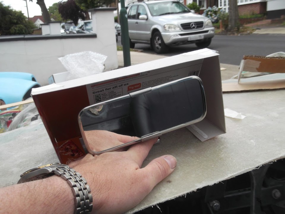
I made a simple template for the base of the aero screens.

This allowed me to test possible fitting options without the risk of dropping the screen itself.
I spent a long time checking underneath the scuttle to see if anything would foul when the screen was fitted above.
But when I finally had a "moment of clarity" I could have saved myself a lot of time.
My problem is that I want to build a "Moon Rover" so I can get the engine professionally checked.
In order to do that I need to fit the dash & the heating system, so it can be plumbed in too.
At this point I would have no access to the under side of the scuttle unless I removed all of these things again.
So what I need is a place where the screens can be bolted to the body shell independently of the "moon rover" structure below.
Which brings me back to mounting the screens on the scuttle "lip" that I looked at briefly before.

I have already marked the outline of the bulkhead on the underside of the body shell.
( Not a great photo. )

So I will be able to strengthen this area when working on the body shell separately.
Next I made some very rough and ready templates for possible wind deflectors designs.
One option is to make these out of metal and then fix them to the scuttle.


This may be a big too big, but it was just to get a rough idea at this stage.

The alternative is to make the deflectors in fibreglass, either as separate pieces, or shapes permanently moulded into the scuttle.
Any thoughts, or suggestions on either option will be gratefully received.
Until next time, take care, Paul.
|
8th July 2014, 18:14
|
|
Senior Member
|
|
Join Date: May 2013
Posts: 2,161
|
|
Nice work Paul.
When I cut my bonnet support brackets off the front chassis bumper, (way back) I had to weld up the steel behind them too. It seems a common problem, but the chassis bumper is stronger afterwards!
|
8th July 2014, 19:41
|
|
Senior Member
|
|
Join Date: Apr 2012
Posts: 1,163
|
|
Funnily enough the only rot on my chassis was also the area behind the 2 bonnet supports when removed, luckily my chassis is a MKIII so the bonnet supports were tiny as was the area of rust. Paul, just about to post on a marathon measure and head scratch athon re bonnet this afternoon  |
8th July 2014, 20:36
|
|
Senior Member
|
|
Join Date: May 2013
Posts: 2,161
|
|
Hey Mac,
I've not used foam much, and don't have a lot of experience with it, but do intend to use a fair ammount of it, sealing between the two skins on my build.
How is it packaged/ sold/ used etc? can you recommend any type, or have links to the stuff?
I have only used one tube type thing, with a nozzle and a button on the top, chuck away afterwards.
Would welcome any advice you may have.
Scottie
|
8th July 2014, 21:06
|
|
Senior Member
|
|
Join Date: May 2013
Posts: 2,161
|
|
Thanks Mac, I'll check it out.
Sorry to nick your thread Paul!!
|
9th July 2014, 07:16
|
|
Senior Member
|
|
Join Date: Feb 2012
Location: Wembley, London
Posts: 5,056
|
|
Scottie & Mac - It does seem there were a lot of "rust traps" built into the Spitfire design.
Scottie - No need for an apology mate, as you, Mac and Mr T are the three biggest supporters of my build.
Mac - Keep forgetting to say I went back to your previous link and found the "hammer test" video clip, very impressive.
- - - - - - - - - - - - - - - - - - - - - - - - - - - - - - -
Last Night...
Whilst I didn't work on the car, I did watch two clinical displays of skill.
The first was on the TV, as Germany made Brazil look like a pub team.
The second was on my daughter's lap top, as Mac posted his laser guided assessment of the Cordite/Navigator bonnet.

This really is a big help for me, as it provides a "sanity check" that I am not doing something wrong when I can't seem to line things up.
It also confirmed that the bonnet (& body shell) must cover the wheels/tyres for the MOT (something I was meaning to check up on).
But I will "pick my battles" to avoid too much work and simply leave some of the symmetry issues as they are, under the terms of "Project Hillbilly".
Cheers, Paul.
|
9th July 2014, 15:21
|
|
Senior Member
|
|
Join Date: Feb 2012
Location: Wembley, London
Posts: 5,056
|
|
A bit more testing...
Too many other things going on at the moment to really get stuck into car work at the moment.
Although, like a moth to the flame, I did find myself doing a bit more mocking up today.
I very loosely fitted the upper steering column and the lovely steering wheel that came with my donor.

Whilst I was confident that it would clear the scuttle, I had to double check before finishing that area off.
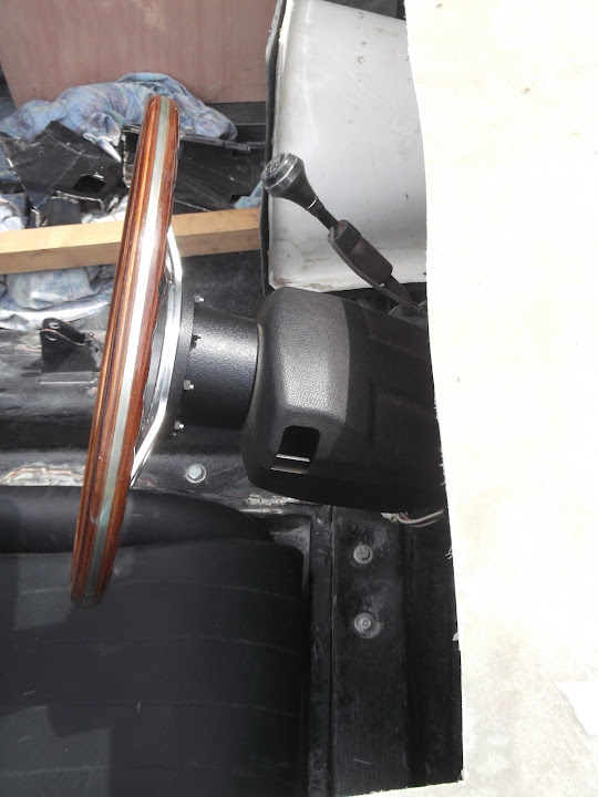
I just need to find the indicator stalk to ensure that can be used without catching the scuttle.
Note: I'm not sure the the Spitfire's plastic column cover looks very vintage.
So I may even attempt to make something myself out of metal at some point.
With the steering wheel in place, climbing into the driver's seat gets a bit trickier.
But this is the driver's eye view of the dash area.

And while I was sitting there, I checked I could reach 1st & the heater controls that will sit under the dash.

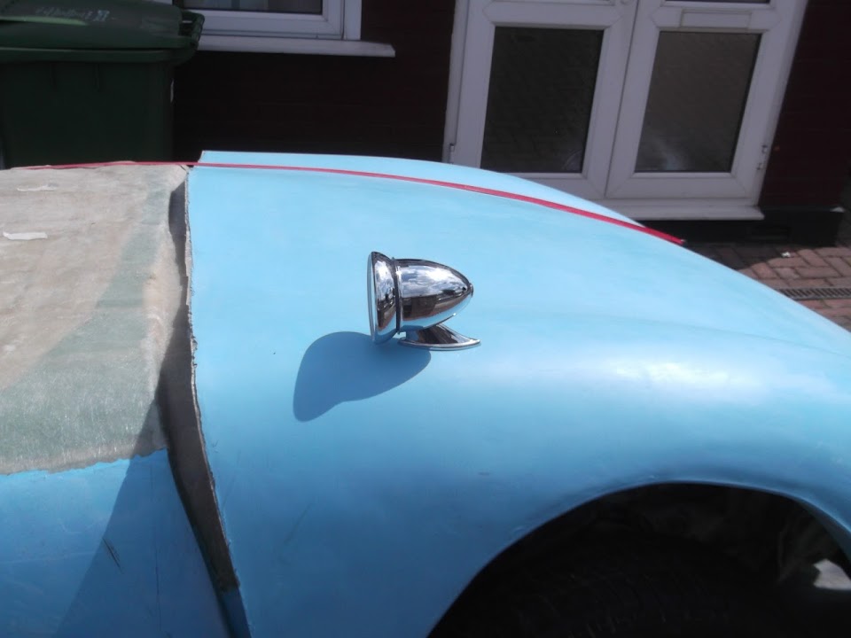
Then I quickly put an aero screen back roughly in place.

Note:
The screen will sit a little higher when attached to the mounting brackets.
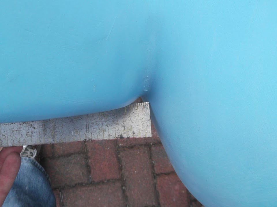
I had another look at the depth that the scuttle currently over hangs the Spitfire bulkhead (the red line).


It looks like there is enough room to fix the screen mounting brackets.
The final shape of the cockpit corner may add a little to the space available for the "outside" bracket.

I will spend a bit more time working out the final design of the cockpit/scuttle edge.
This work is also linked to how the cockpit gets panelled out as I still need access to mount the side mirrors.
That is unless I stick them on the bonnet and leave the scuttle area alone.
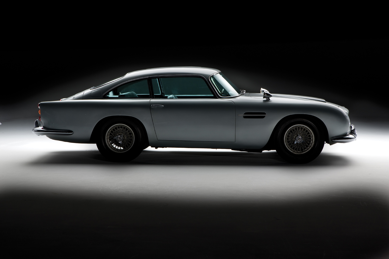
I need an extra pair of hands to check if I would be able to see anything with the mirrors here.
Whilst it doesn't look like many Sammio builders have gone for this option, clearly other cars have.
( I know the DB5 doesn't have a flip up bonnet, but I mean how far forward the mirrors are placed. )
Anyway, that's all for now, as I am supposed to be doing something else!
Take care, Paul.
Last edited by Paul L; 9th July 2014 at 19:14..
|
9th July 2014, 21:10
|
|
Senior Member
|
|
Join Date: May 2013
Posts: 2,161
|
|
Paul, a lot of cars from the 50's and 60's had mirrors way far forward on the front wings, and the biggest problem with that was, you can't see bugger-all in them! They are so far away, the image is just too small to see.
I plan to have my mirrors ( when I get that far) as close to my face as I can, to give me the best chance of seeing anything!
|
|
Currently Active Users Viewing This Thread: 1 (0 members and 1 guests)
|
|
|
 Posting Rules
|
You may not post new threads
You may not post replies
You may not post attachments
You may not edit your posts
HTML code is Off
|
|
|
All times are GMT +0. The time now is 19:25.
|


 Linear Mode

