|
|
| Sammio Builds and discussions Sammio bodied car builds and specials |

13th September 2015, 19:03
|
 |
Senior Member
|
|
Join Date: Dec 2013
Posts: 839
|
|
I take my hat off to you Paul for using the original loom and figuring out what is required, i took the easy option and went for an after market loom.
Good luck.
|
15th September 2015, 12:53
|
 |
Senior Member
|
|
Join Date: Feb 2012
Location: Wembley, London
Posts: 5,056
|
|

Micky1Mo & Swifty - Cheers Chaps. 
There are definitely both pros & cons associated with using/modifying the original Spitfire loom.
But at least I was able to test all of the lighting circuits "indoors", which was a big help.
- - - - - - - - - - - - - - - - - - - - - - - - - - - - - - -
Monday:
Good timing meant that I didn't work on the car and get caught out with the sudden downpours that rolled in throughout the day.
But bad timing meant I was actually out on my push bike when one of these storms arrived out of nowhere and I got drenched. 
( Riding through traffic with hail coming down so hard it actually hurts, is not my idea of a good time! )
- - - - - - - - - - - - - - - - - - - - - - - - - - - - - - -
Tuesday:
Good timing today meant I picked one small job to do and managed to be done and dusted before the rain arrived again.
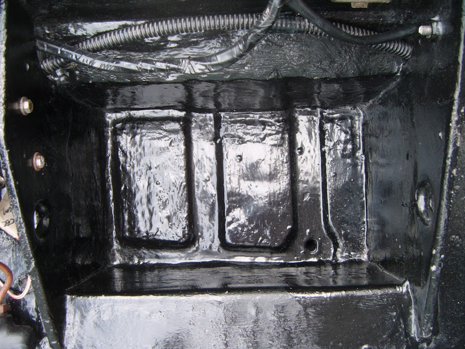
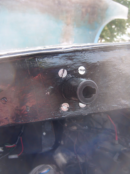
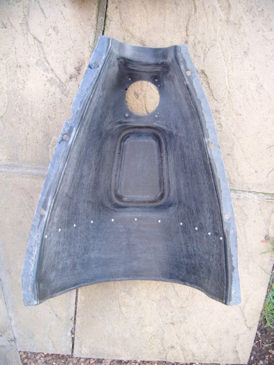
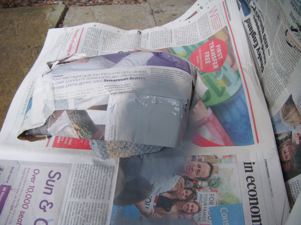
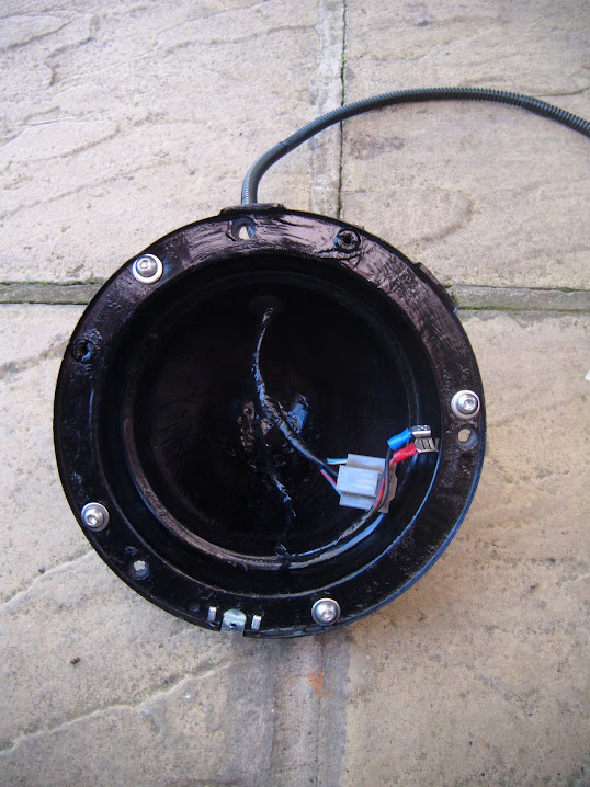
While looking at the wiring loom in the boot area I remembered that I still needed to fit the cover over the suspension mounting bolts.
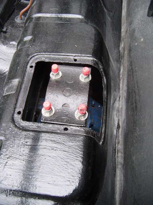
You may remember that fitting the lowering block makes this area sit proud of where the original Spitfire cover would sit.

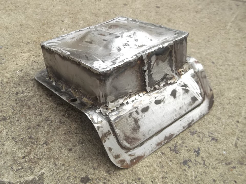
Way back in May 2014, I did the modification work required to turn the original Spitfire cover...

Into Frankenlid...

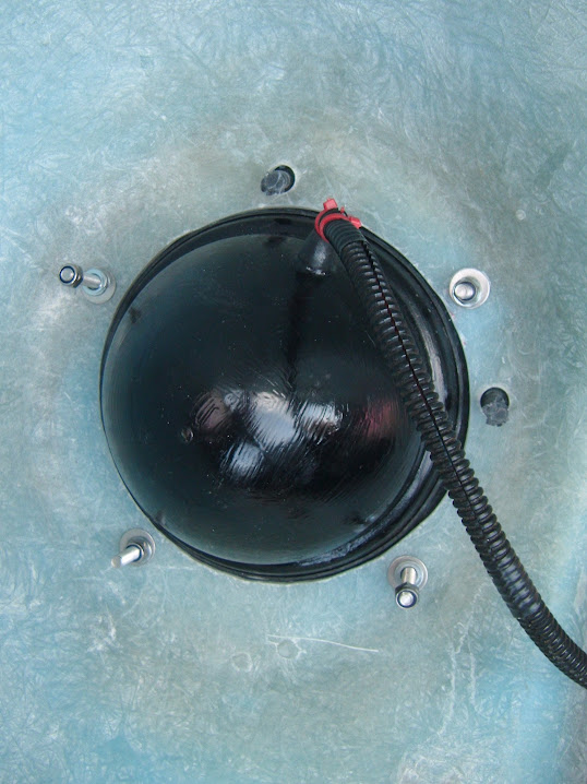
So I put the screw fixings into position and added a layer of sealing compound.

Tightened the 4 screws and spread the squeezed out sealing compound along the edge of the join.

It just needs a final lick of paint.

It is funny how the little jobs like this one & connecting the fuel lines really feel like big steps forward for this build.
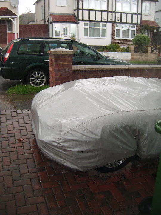
Unfortunately, at this point the sky was getting darker...

But thankfully all the covers were back on and I was safely back indoors when the next storm hit.
- - - - - - - - - - - - - - - - - - - - - - - - - - - - - - -
New Registration Number:
I have been toying with the idea of getting an "ageless" number plate ever since I started this project.
My donor Spitfire was a 1980 "V" reg, which makes it one of the youngest Sammio/Ribble/Milgia builds on here.
However, the long running saga of getting my original V5C updated put this idea on the back burner for a while.
I had looked into the cheap NI Plates and had thought a "MIG" plate would work well, given all the bulkhead welding I did.
( This was actually before WCA and some of the other Tribute builders "next door" start getting them. )
As I could never find a traditional UK ageless plate (3 number & 3 letters, in either order) at a reasonable price.
However, Mister Towed posted something a while back on a different thread & I've shamelessly stolen his idea.
So rather than go for an "ageless" plate, I've actually just bought an "aged" plate from 1965, a suffix "C" reg.
Again, this was a great bit of timing, as this particular number only appeared on the website a few days ago.
( It was sold on behalf of a customer, so it was cheaper than normal & comparable with a NI "MIG" plate. )
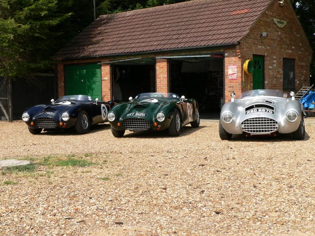
After all, in this classic line up photo below, Phil & Barry both have "H" regs and Mr T himself has a "G" reg.
Given that I've always aspired to join this line up one day, at least now I will not be the odd one out with a "V" reg.
Perhaps I should claim that my car was an early "prototype", which was refined into the curvy Spyder design in later years. 
I know there have been debates about using vintage B/W "show plates" on cars that don't qualify for the old style.
Well, I've decided to stay "rat legal" and use yellow and black at the rear, but with raised letters.
Something like this.

One day I would like to attend the Goodwood Revival and hopefully these little touches will help me blend in.
- - - - - - - - - - - - - - - - - - - - - - - - - - - - - - -
Period Racing:
Talking of Goodwood, I found these two short video clips on their website.
https://grrc.goodwood.com/goodwood-r...S7QOt6roEUt.97
https://grrc.goodwood.com/goodwood-r...8bxF0iuSBhf.97
These highlight the range of shapes available at the time.
Given how my build is finally shaping up, I am happy that I will end up with something that would not look out of place.
Until next time, take care, Paul. 

|
16th September 2015, 10:31
|
|
Senior Member
|
|
Join Date: Apr 2014
Posts: 198
|
|
Hi Paul, one of the young lads in the Jeep club had pressed steel number plates on a 1985 Suzuki sj in yellow/white black they even had supplying Suzuki dealer name on them, looked to me like they where fitted new and he got a ticket and points for both front and rear? I said at the time he should protest it as surely you can't be forced to retro fit items to comply. But as he had just fitted a 1.6 Vitara engine in it and it was still registered as a 1.0 and he hadn't told the insurance about his new winch and big tyres he thought it wise to just pay up. I think a picky traffic cop would have you especially if they looked into purchase/ transfer date. Saying that there is a Porsche Cayenne down the road from me with proper blacked out front side windows and pressed steel black and silver plates on a 57 plate no supplying dealer info he also has bright blue led side lights. There was also a newish e class merc complete with shoddy white vinyl wrap that flapped about showing the black underneath and that had a diffent reg number on the front to the rear for many months. So maybe nobody cares anymore. I once got a ticket for having an odd number of spotlights on the front of my car.yet a few years back you could buy a new mini Italian job with 3.Ed
|
16th September 2015, 14:48
|
|
Senior Member
|
|
Join Date: Feb 2012
Location: Wembley, London
Posts: 5,056
|
|
Ed - Thanks for the heads up.
The rear plate will be black plastic characters on a reflective yellow background.
( I will be using a stick on number plate on the front. )
I was told this style is perfectly legal on pre-2001 cars, so I should be OK. 
Cheers, Paul.
|
17th September 2015, 16:33
|
|
Senior Member
|
|
Join Date: Feb 2012
Location: Wembley, London
Posts: 5,056
|
|
Wednesday: - A wash out in terms of the weather, and I wasn't feeling that great either. 
- - - - - - - - - - - - - - - - - - - - - - - - - - - - - - -
Thursday - Part 1:
Whilst I still wasn't feeling 100%, at least the weather had improved.
I picked some simple tasks that didn't require much physical effort, but even these ended up being time consuming.
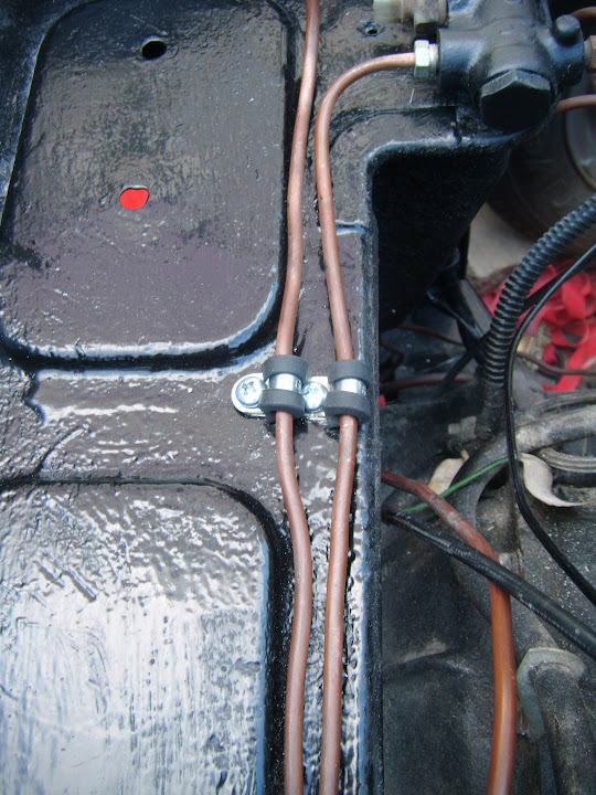
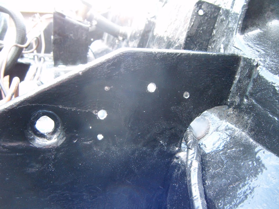
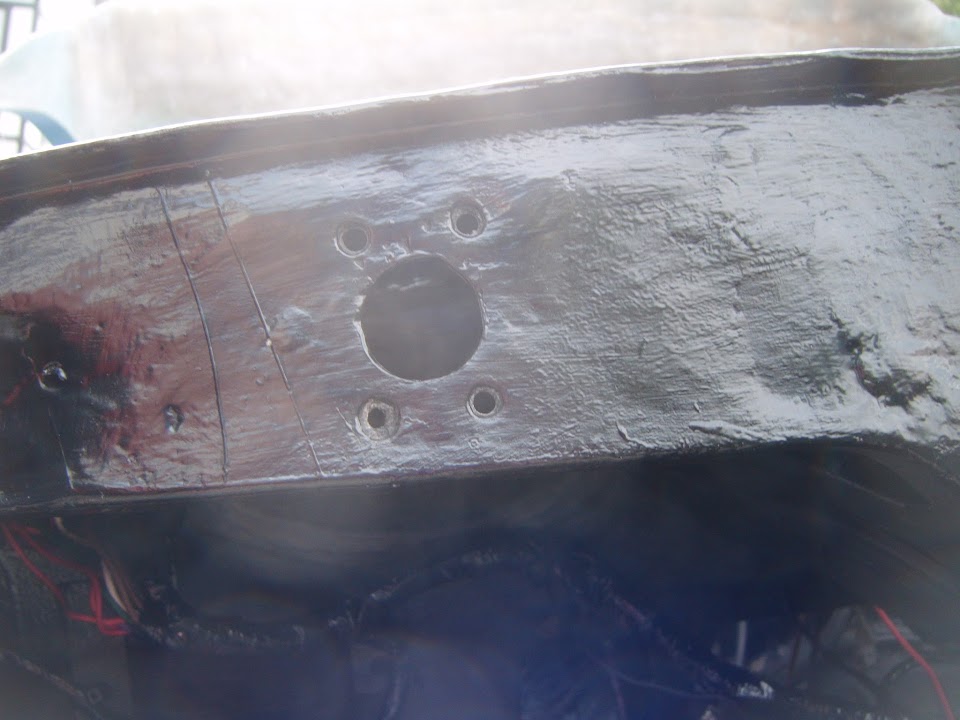
Drilled a new hole in the bulkhead to re-attach the P clips for the brake hard lines that came with my donor.
( There was a fixing hole in my original 1500 bulkhead, but not this MkIV one. )

I also drilled some more holes along the bulkhead "shelf" and fitted some new "P" clips for the clutch and brake lines.


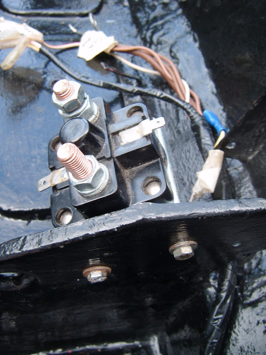
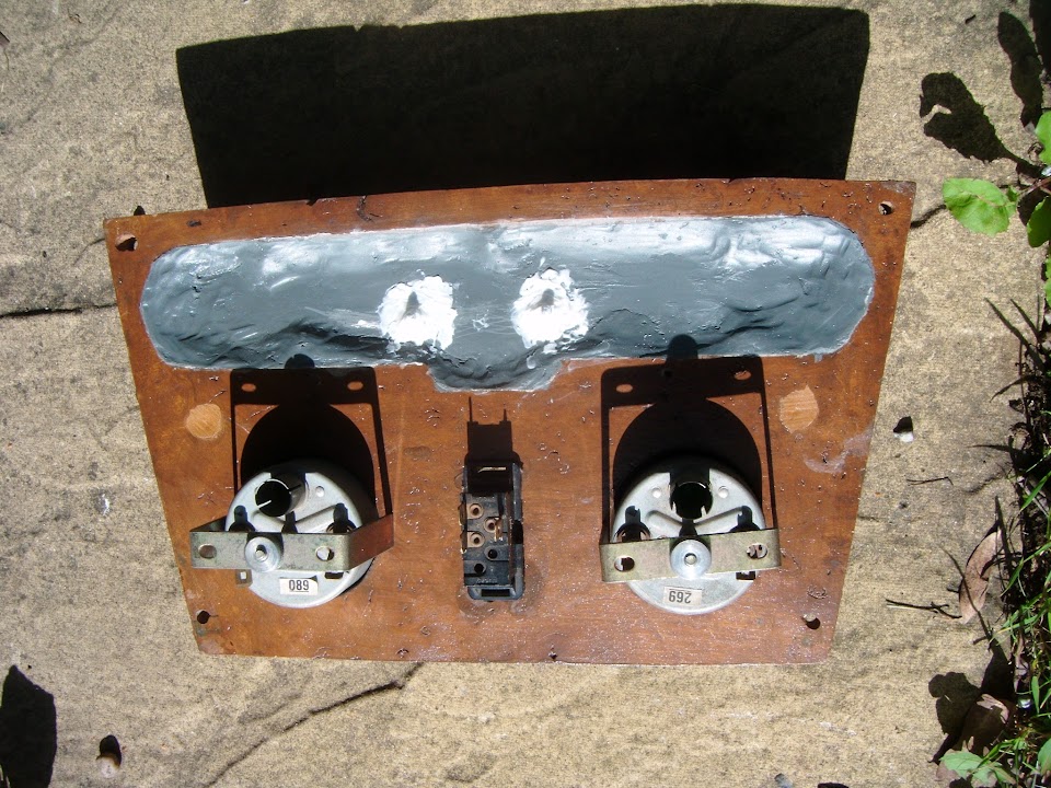
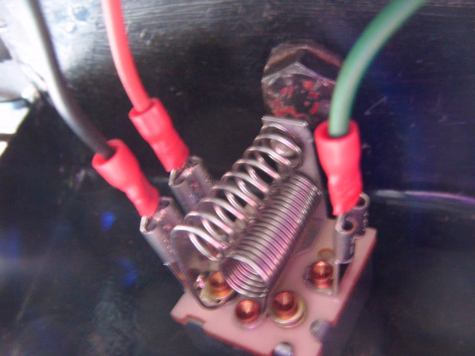
The fixing points for the starter solenoid were also wrong on this bulkhead.

So two new holes were drilled and this could be fitted too.
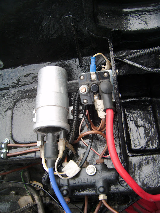
Next was the ignition coil, after I spent a ridiculous amount of time trying to find the original fixing bolts for it. 
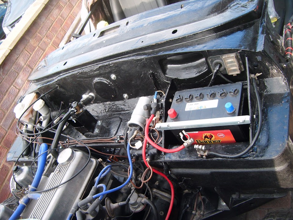
I put a rubber mat in the bottom of the battery tray, before fitting the new battery.
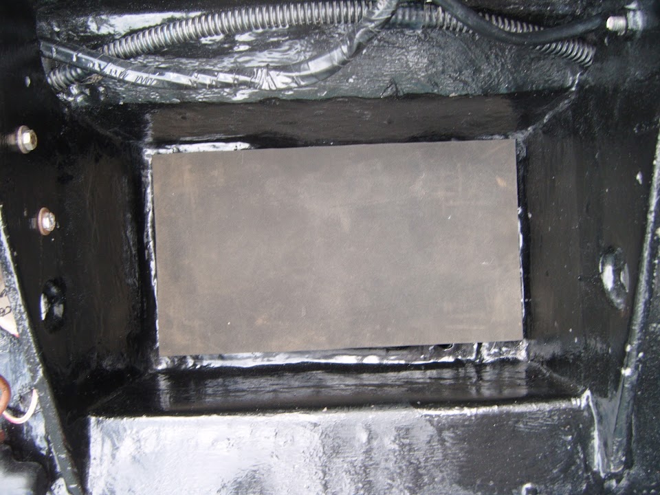
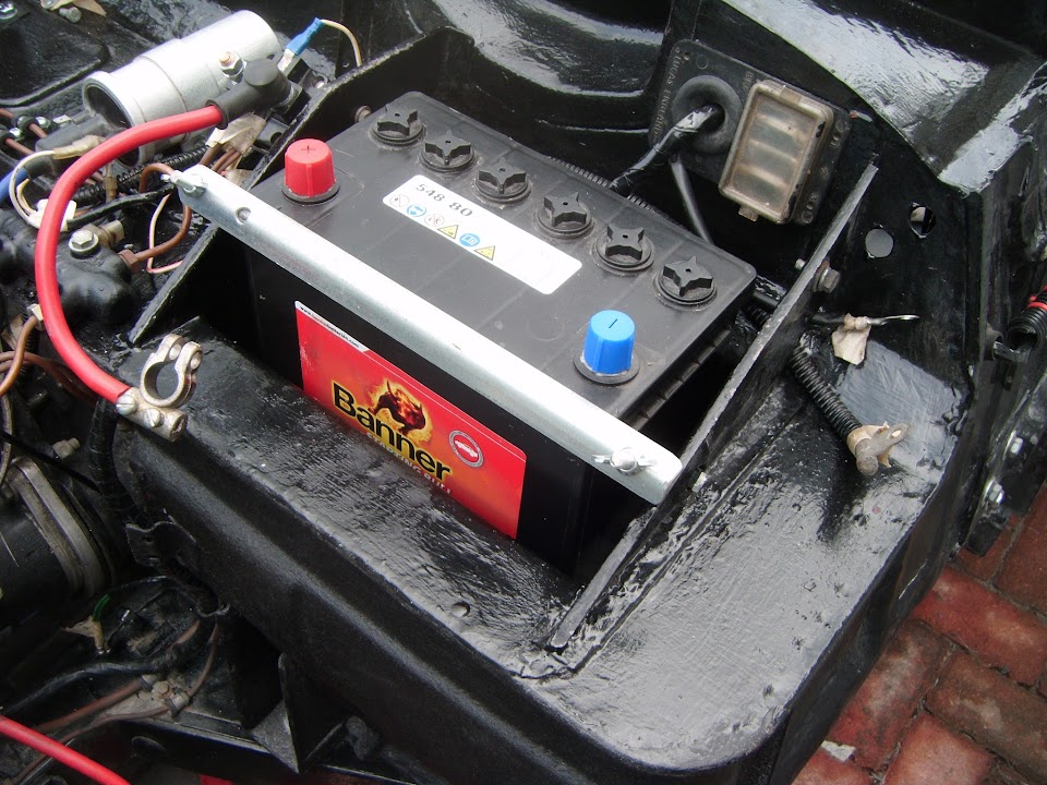
I've decided to refit the original Spitfire battery earth cable, until I have got the engine running again.
As this will remove any uncertainty about the new battery cut off switch causing any problems.
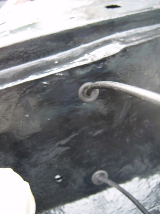
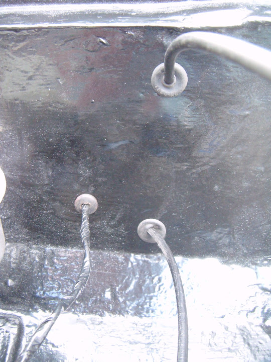
So for now, there are three wires earthed at the side of the battery box.
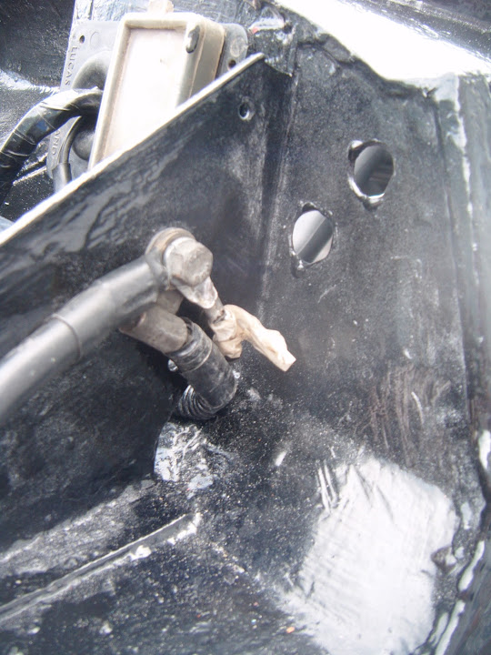
Note:
The two holes in the bulkhead are where the cut off switch cables will be go.
Next the car horns were fitted, starting with the mounting brackets.
Then the horns could be attached to them.

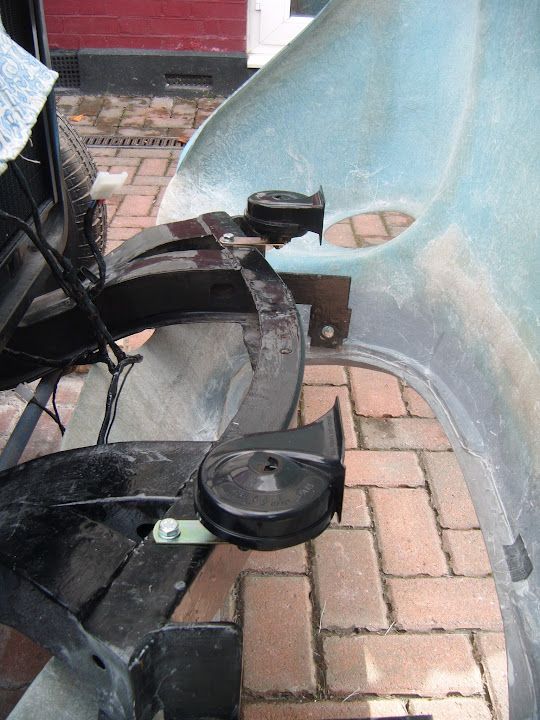
They will both be pointing straight out of the front grille, so should be 'loud and clear'.
Note:
These are new car horns that came with my donor, but hadn't been fitted.
So if I've done something wrong in either where I've fitted these, or how I've fitted them, feel free to let me know.
End of Part 1...
|
17th September 2015, 16:34
|
|
Senior Member
|
|
Join Date: Feb 2012
Location: Wembley, London
Posts: 5,056
|
|
Thursday - Part 2:
I finally got around to putting some thick cardboard in front of my new radiator.
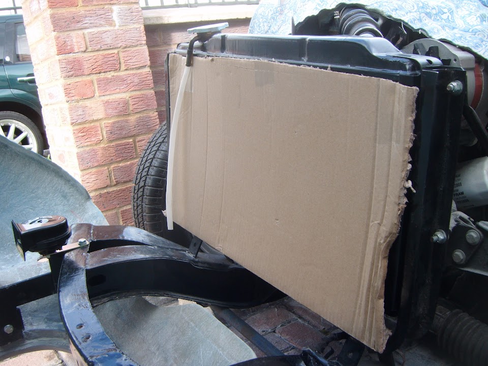
Hopefully this will help prevent any accidental damage during construction.
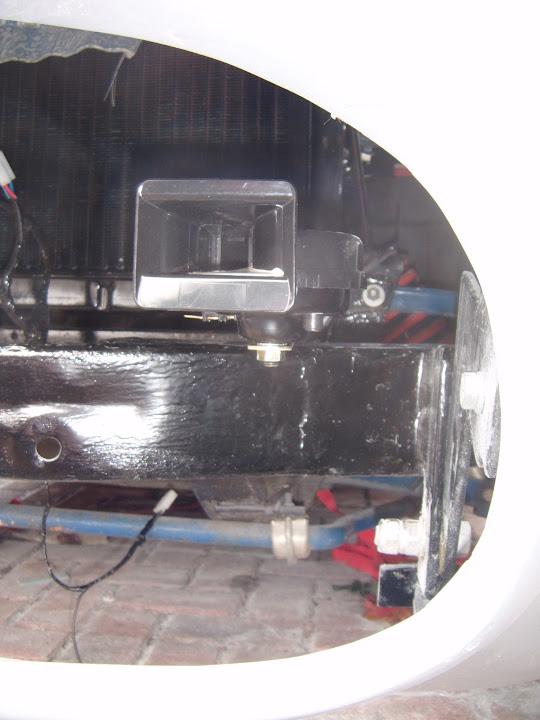
Even though I will not be connecting this up just yet, I did fit the cut off switch.
The restricted access at the back made this much harder to do than it should have been.
For now, I've just put the switch cover in place until the wooden dash board section gets fitted.

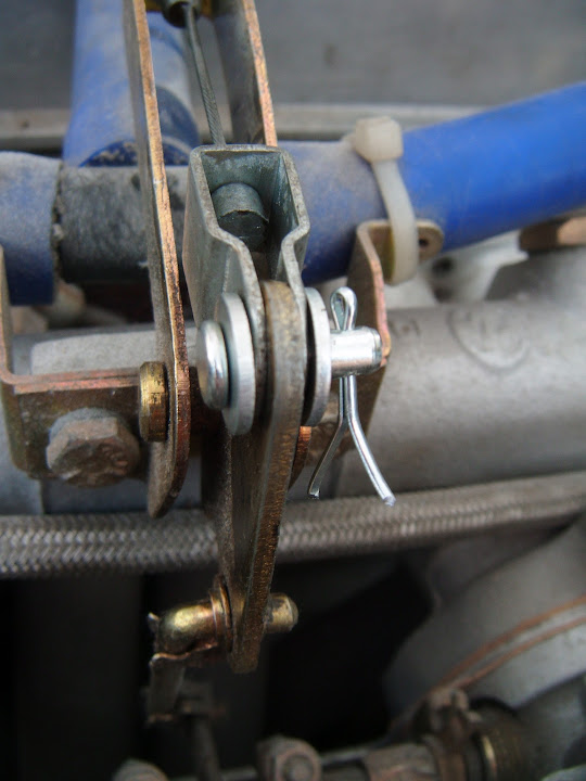
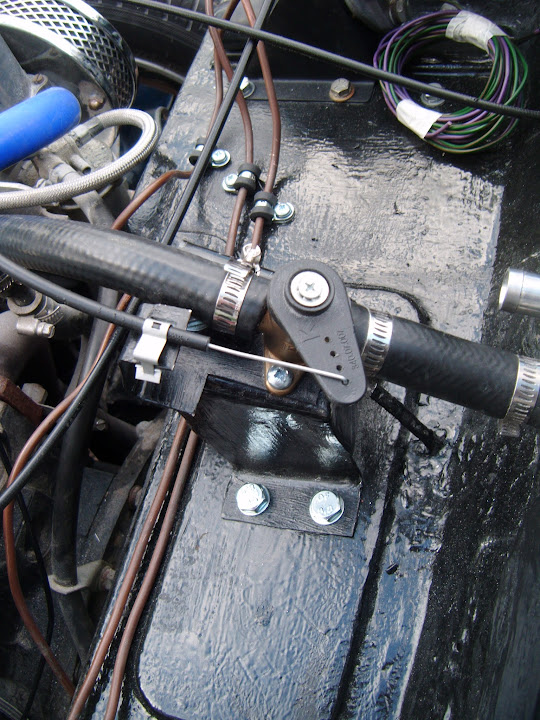
I made a small funnel to get some 3-in-1 oil all the way through the throttle cable.
Then the cable fitted through the bulkhead and connected to the accelerator pedal.
I was then able to fit the new pivot pin parts at the other end.
( Replacing the original parts that were lost/missing. )
Overall, lots of small jobs, but it does feel like I am finally working my way towards the "Moon Buggy" stage.
So until next time, take care, Paul.
|
17th September 2015, 20:43
|
|
Senior Member
|
|
Join Date: Apr 2014
Location: Midlands
Posts: 405
|
|
Wow Paul, I'm tired reading how much you have achieved! Might be small jobs individually but combined as a single piece of of work plenty enough for one day.
I hope you feel 100% again tomorrow . Ian
|
18th September 2015, 16:30
|
|
Senior Member
|
|
Join Date: May 2013
Posts: 2,161
|
|
Its coming together nicely Paul. :-)
|
18th September 2015, 16:51
|
|
Senior Member
|
|
Join Date: Feb 2012
Location: Wembley, London
Posts: 5,056
|
|
Jones & Scottie - Thanks gents.
Whilst there is always frustration when small jobs take longer than they should, this is still a good step in the right direction.
As connecting up the wiring loom, fuel lines, gauges, etc. is the path to getting the engine re-started and, in turn, the body shell bonded on.
- - - - - - - - - - - - - - - - - - - - - - - - - - - - - - -
More Small Steps Forward:
I had to wait for the mist to clear in the morning before I could start work.
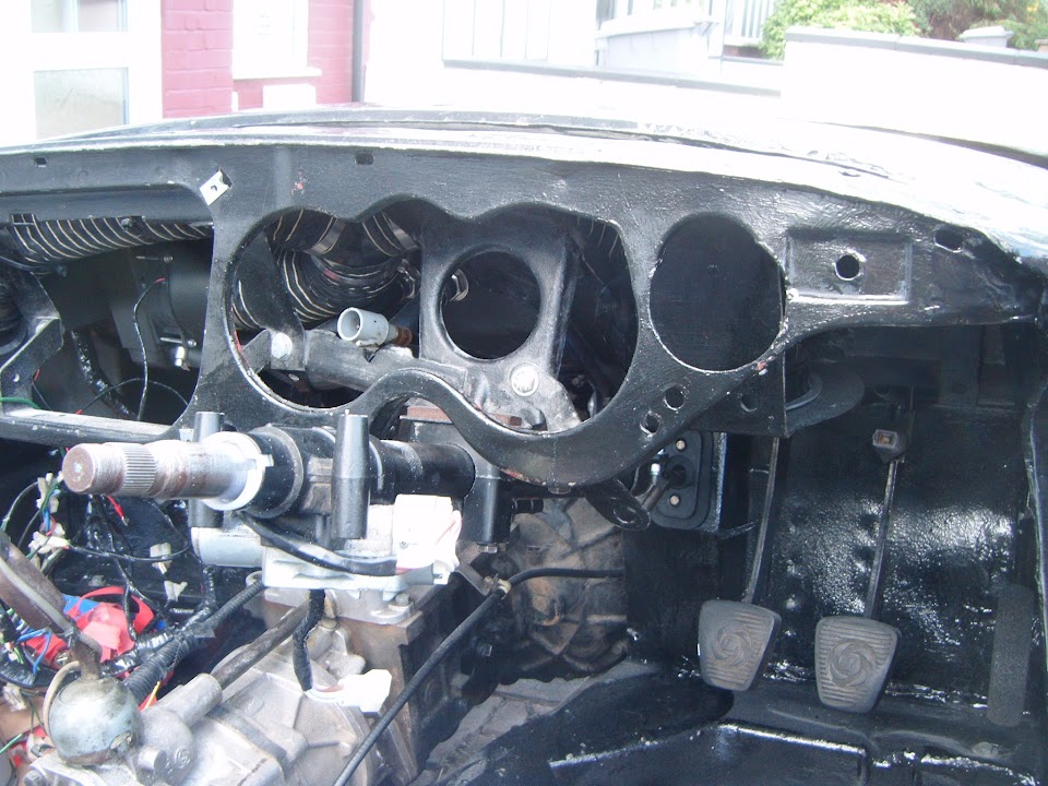
Removed the steering column cover, indicator switch & dash board section to get better access to the bulkhead behind.
I had one slight hiccup doing this, when I dropped one of the retaining "nuts" for mounting the speedo out of the cockpit & under the car. 

Unfortunately, despite looking for ages, I just could not find where it had rolled to.
Thankfully my donor came with boxes of "bits & pieces" and I did find a spare one that I can use instead.
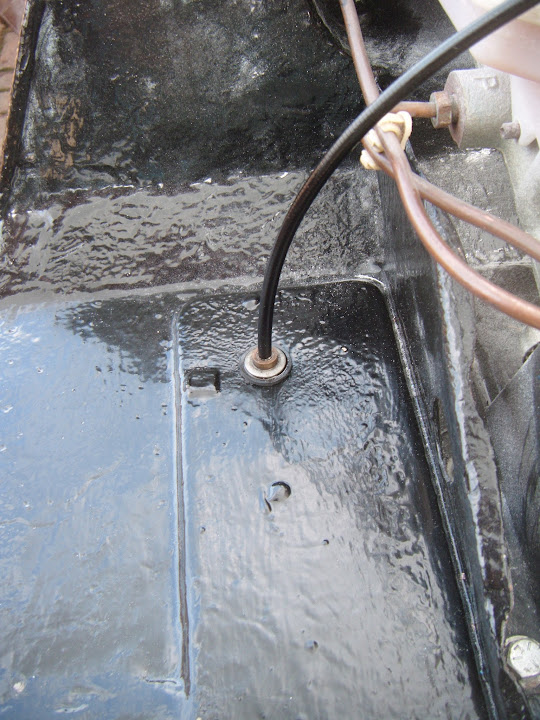
Then I fixed my new choke cable to the dash.
Before threading the cable through the heater vent panel...
And out through the bulkhead.

After initially connecting the cable end to the carbs, I realised I needed this to be detached while I worked on the rest of the dash.
( To allow the panel with the choke level attached to be moved around. )
The next cable to come out of a storage box was for the heater control valve.

This exits through the bulkhead above the choke cable.
Then it was the turn of the wires for the new oil pressure gauge.

Although at this point, there is nowhere to attach the other ends of these wires to.

However, in order to get a working Moon Rover, I just need the wiring behind the dash to be sorted out, so that is fine for now.
Initially I got confused by these two relays...

As I could only find a fixing for one of them behind the dash (excuse the poor photo).
It was only after searching in vain for a second fitting that I spotted this on the bottom of one relay.

Which would allow it to slot into this hole in the dash.

And sit next to the other relay like so.

Note:
Now I know where these will be fitted, I can finish wrapped up the wires, as they were left during my previous indoor testing.
End of Part 1...
|
18th September 2015, 16:53
|
|
Senior Member
|
|
Join Date: Feb 2012
Location: Wembley, London
Posts: 5,056
|
|
Part 2
I then spend a lot of time working out the best route for the wiring loom to connect everything up behind this section of dash.

I was just starting to carefully push the dash section back into place...

When my Spyder Senses started tingling, as the temperature dropped and the sky went dark...

Thankfully I was just fixing the cover in place when the rain started and within a minute of getting inside it absolutely hammered down! 
Unfortunately, other stuff & the weather got in the way for the rest of the day, until I was able to do a bit in the Summer House.
I marked up and drilled out the holes required for the fixing pins of my 1500 badge.

Eventually, the badge will go here.
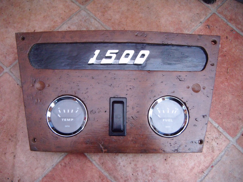
But first I wanted to give a final coat of paint to the panel itself, after masking everything else off.
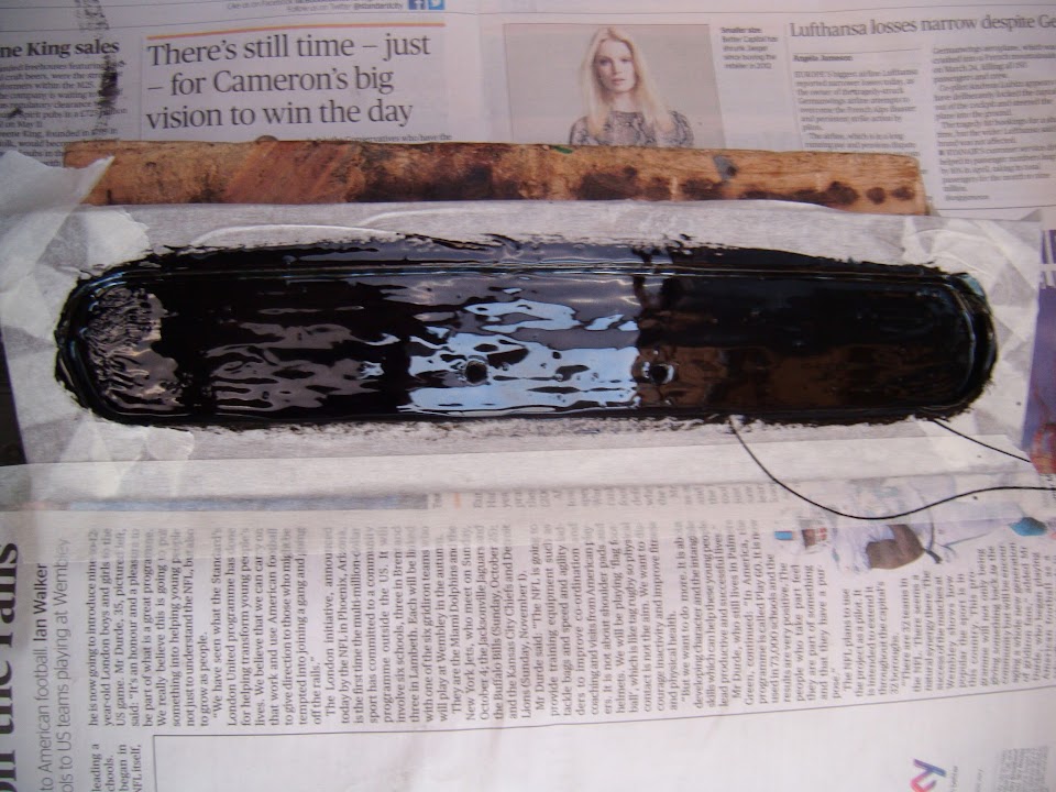
I also gave the panel for the heater controls a final coat while I was at it.

Hopefully I will get a bit more wiring done over the weekend.
So until then, take care, Paul.
|
20th September 2015, 05:20
|
|
Senior Member
|
|
Join Date: Feb 2012
Location: Wembley, London
Posts: 5,056
|
|
Yesterday - Part 1:
Saturday turned into quite a long and hectic day, as I tried to juggle family life with working on the car.
Thankfully the weather held, so I managed to get quite a lot done over several separate sessions, ranging from minutes to hours.
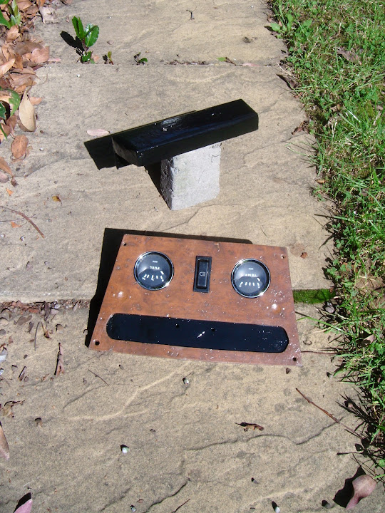
First job of the day was to leave the stuff I painted yesterday out in the sunshine.
( Just to be sure they were dry enough to play with later on. )
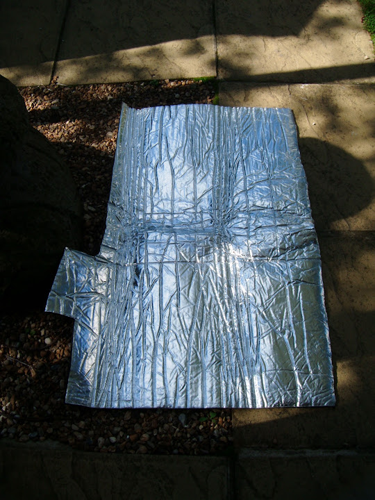
Then, in order to continue with the cockpit wiring, I pulled out the gearbox cover.
Although it is not the cover I was interested in, but the heat reflective foil I bought to cover the inside.
I cut out & fitted the first few pieces.


Then finished it off.

This way, I knew that the "left overs" could be used behind the dashboard to protect the wiring later on.
But while I was at the bottom of the garden I pushed the 1500 badge into position.
It is actually a tight, friction fit, but I added a couple of blobs of glue to the badge pins just to be on the safe side.
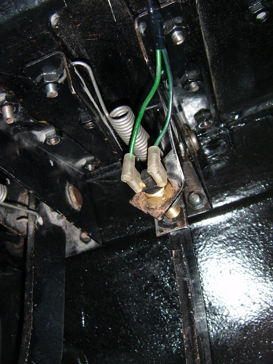
I also dug out the new metal brake light switch, which is marginally thinner than the plastic original.

I spending ages crawling around in the foot well, upside down, trying to fix the main dashboard section in place.
I lost count of the number of times I caught my back on something, banged my head, or hacked my fingers.
In the end, I was so relieved when the dash was in, that I forgot to take a photo until later on.

I did discover one snag, as the connection block on the new ignition wiring didn't match the old connector in the loom.
So I need to come back to sort that out at some point and I just carried on with the rest of the loom.
The more I looked at it, the more I was convinced that the relay with the clip catch wouldn't actually stay in position.
There was one hole in the dash nearby, so I drilled another and added a zip tie to help the clip do its job.

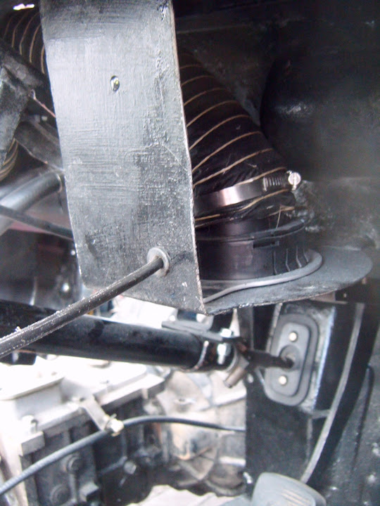
Then I wrapped some of the heat reflecting foil around the heater and the vent hoses.
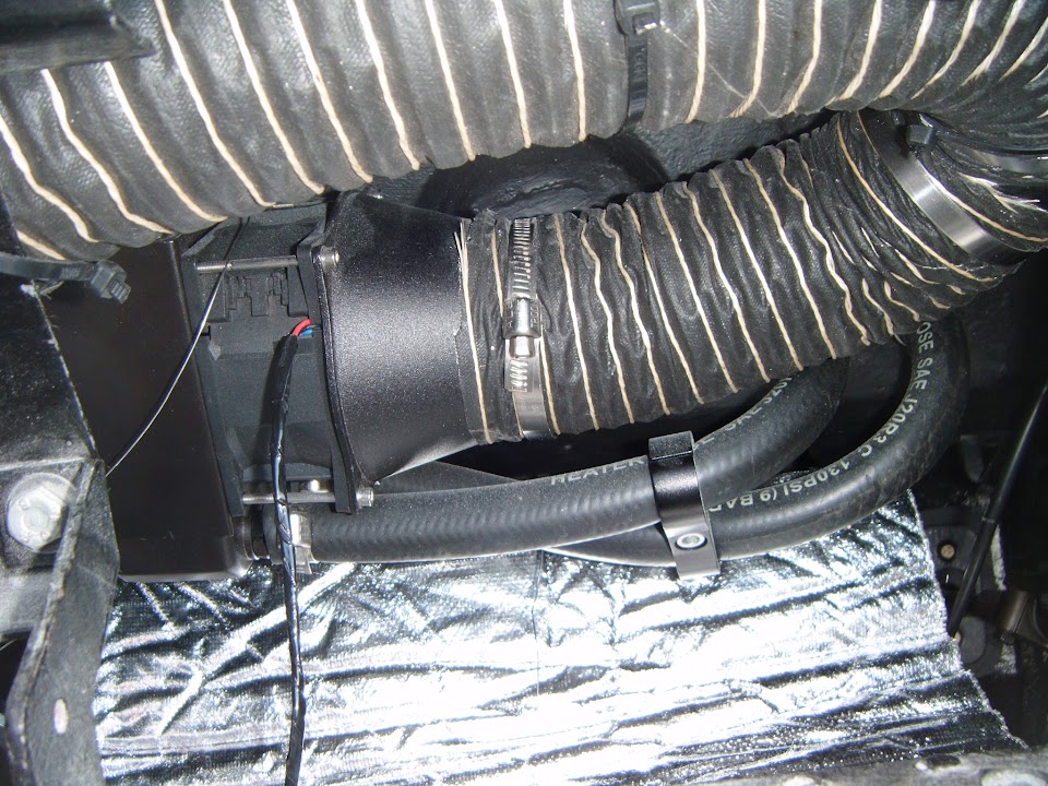

This is not a great photo, but the area behind the main dash panel has also got some protection now.
Whilst I am sure this approach is a bit OTT, and not strictly necessary, I hope it will help.
I just added a washer to one side of the new brake light switch and that went in fine.
The left hand section of the dash went in with no problems.

Note:
The wires hanging down are where the rear loom attached and these have now been properly connected and tucked out of the way.
End of Part 1...
|
20th September 2015, 05:25
|
|
Senior Member
|
|
Join Date: Feb 2012
Location: Wembley, London
Posts: 5,056
|
|
Yesterday - Part 2:
Eventually I had zip tied the bulk of the loom into position, ready to fit the centre section.

Hopefully the use of the heat reflective foil will protect this main section of the loom from being "cooked" when the heater is on.
But before I could fit the central dash section in place, I had to fix the heater control panel that sits below it into position first.
The centre section was the easiest bit of wiring I did all day.

Although fitting the panel itself turned into a complete pain, as the last screw would just not line up.
So I had to remove all the other screws and start again from the troublesome corner and it worked this time.
( Excuse the run of poor photos I seem to have. )

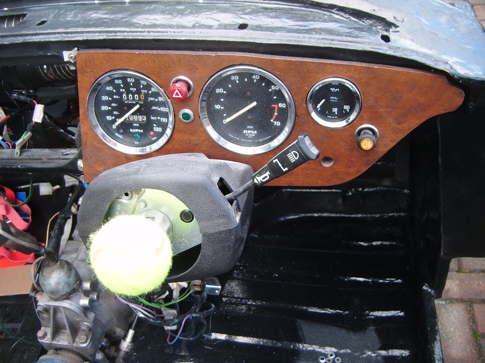
So now all three sections of the dash board were in position.
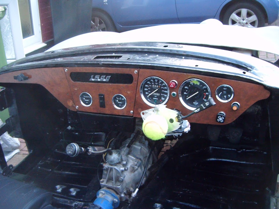
And before I packed up for the night, I couldn't resist pushing the steering wheel into place.

I just hope everything works as well as it looks. 
- - - - - - - - - - - - - - - - - - - - - - - - - - - - - - -
Dashboard - "To Do" List:
- Fix the mis-matched ignition wiring connection.
- Sort out the wiring for the heater fan speed switch.
- Connect the heater control dial to panel and attached to control value.
- Seal off space for wiper controls on steering column cover & re-fit.
- Attach end of choke cable to carbs.
- Plumb the heater into engine (OK, technically, that is on the bulkhead list, but is kind of related).
- - - - - - - - - - - - - - - - - - - - - - - - - - - - - - -
With a bit of luck I will get the chance to do some of these jobs later today.
Cheers, Paul.
|
20th September 2015, 06:33
|
 |
Senior Member
|
|
Join Date: Jun 2011
Posts: 935
|
|
Its coming along in leaps and bounds now Paul.
Dash and steering wheel look the part |
20th September 2015, 10:52
|
|
Senior Member
|
|
Join Date: Jun 2011
Location: birchington, kent
Posts: 1,769
|
|
A Dash, seat and steering wheel, when lunchtime comes I would be having my sandwich and tea sat in the car...
|
20th September 2015, 17:16
|
|
Senior Member
|
|
Join Date: Feb 2012
Location: Wembley, London
Posts: 5,056
|
|
Roadster & Gary - Cheers chaps.
After so long spent trying to work out how to build this car, it does feel good to be actually putting parts back on.
- - - - - - - - - - - - - - - - - - - - - - - - - - - - - - -
Slowly Getting There - Part 1:
A slight change of plans today, as two nice days in a row saw me oiling the garden furniture before the real bad weather arrives.
I also ended up mowing the lawn and doing a number of other domestic chores, but at least I did get some car time...
I actually managed to work my way through most of the "To Do" list I posted yesterday:
Plumb the heater into engine
This should have been straight forward, as I had previously just by-passed the old heater like so.

I cut that hose down so that I could re-use it to connect to the heater control valve.
( Having previously double checked old photos to ensure I knew which hose went where. )

Then the wheels came off as I realised I had a mis-match in pipe sizes / hoses.
After a lot of time spent trying to make a 13mm ID hose fit a 16mm ID fitting I had to admit defeat.
So I have now ordered a reducing connector that will allow me to joint the heater pipe to the engine pipe.

As this was the first job of the day, I wasn't happy with how long I'd spent not completing the task.
- - - - - - - - - - - - - - - - - - - - - - - - - - - - - - -
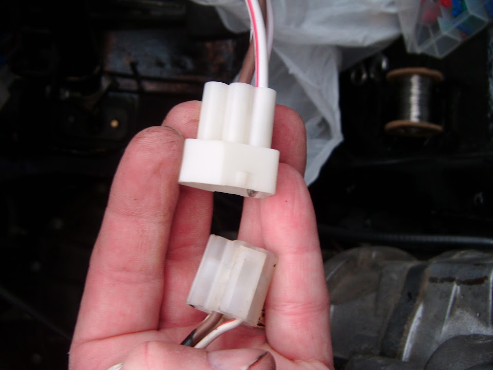
Fix the mis-matched ignition wiring connection
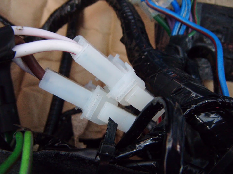
I went through my various electrical "spares", but could only find "double" connectors, rather than "fours".
So I simply used two "doubles", although this first photo is blurred.
Note:
The front indicator was there to remind me which way round the connectors needed to be wired.
With both ends changed, the ignition wires could be joined and tucked up out of the way with the rest of the loom.
- - - - - - - - - - - - - - - - - - - - - - - - - - - - - - -
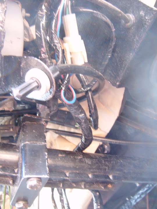
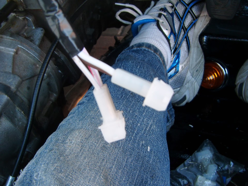
Sort out the wiring for the heater fan speed switch
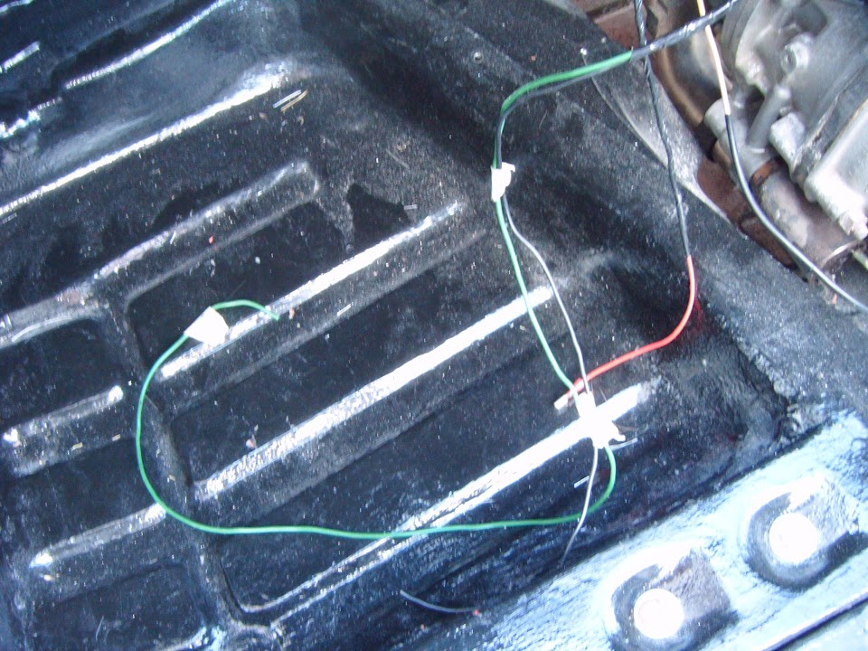
I needed to join up the wires from the loom, the wires from the heater and some earth wires.
Once I had shortened everything to the right size and added the appropriate connectors, it was time to fit the switch.
At which point, my second problem of the day appeared, which was a mis-match between the fixing holes in the panels.
( Two small holes for locating pins and one big hole in the middle. )

After spending some time hand filing the gap to fit, I then realised I actually needed a bigger hole. 
Once that had been sorted out, the switch could be fitted with ease.


And then wired up.
I also drilled a small hole in the metal dash board support for the three earth leads.
( Main loom, heater & heater switch. )

- - - - - - - - - - - - - - - - - - - - - - - - - - - - - - -
Attach end of choke cable to carbs
The most straight forward job of the day.

- - - - - - - - - - - - - - - - - - - - - - - - - - - - - - -
End of Part 1...
|
20th September 2015, 17:17
|
|
Senior Member
|
|
Join Date: Feb 2012
Location: Wembley, London
Posts: 5,056
|
|
Slowly Getting There - Part 2:
Connect the heater control dial to panel and attached to control value
Thankfully this switch could be fitted on the first attempt.


The photo above shows the dial in the fully off position.
This corresponds with the cable being attached to the control valve like so.

Then as the dial is turned to the fully on position...

The valve moves like so.
For the on & off positions to tie in with the red markings on the dial, the cable would have to attach to a different hole on control lever.
However, when I tried to do this, I could not get the cable to line up nicely, so have left it as it is.
( Thankfully this build has killed off most of my old OCD tendencies. )
- - - - - - - - - - - - - - - - - - - - - - - - - - - - - - -
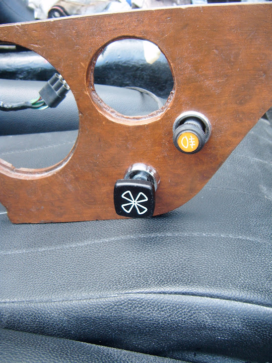
Which now leave the centre section of the dash looking like this.
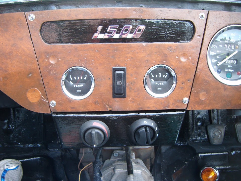
The plan was to make it look like the heater was a new, modern, addition to an old racing car.
( Well that is my excuse anyway. )
- - - - - - - - - - - - - - - - - - - - - - - - - - - - - - -
Which just leaves Seal off space for wiper controls on steering column cover & re-fit on my "To Do" list.
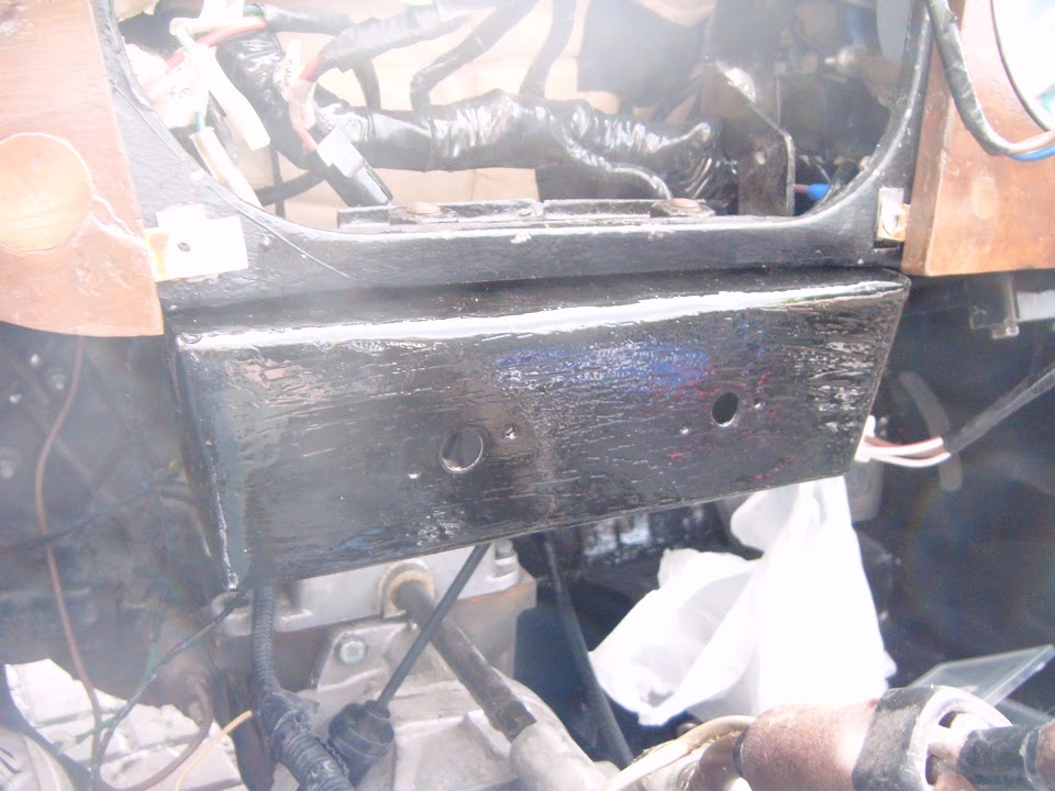
But for now, I will leave you with this photo showing how the bulkhead "shelf" is now looking.
- - - - - - - - - - - - - - - - - - - - - - - - - - - - - - -
Until next time, take care, Paul.
Last edited by Paul L; 21st September 2015 at 05:32..
Reason: Typo
|
21st September 2015, 14:00
|
|
Senior Member
|
|
Join Date: Feb 2012
Location: Wembley, London
Posts: 5,056
|
|
A bit of a wash out:
A combination of rain outside and a daughter off school inside, meant there isn't loads to report today.
Whilst indoors I cut holes in a piece of thick cardboard based on my rear lighting template.

Then put all my rear lighting into position, so they can be tested with the rest of the Moon Rover's electrics.
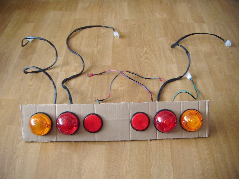
I also finished wrapping up the last few wires while I was at it.
Then to stiffen up the "lighting board" a bit, I added two lengths of plastic conduit to to the top & bottom.
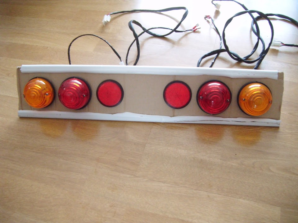
Which just makes it a bit easier to carry around.
- - - - - - - - - - - - - - - - - - - - - - - - - - - - - - -
I did make the tactical error of taking a chance and working outside for a few minutes when it looked dry.
As I had pulled out the radiator overflow bottle I ordered years ago to replace the one that was missing from my donor.
Looking at other photos would suggest this hole in the radiator mounting bracket is where it is supposed to be attached.

But no sooner had I started to tighten up the bolt when the rain returned.

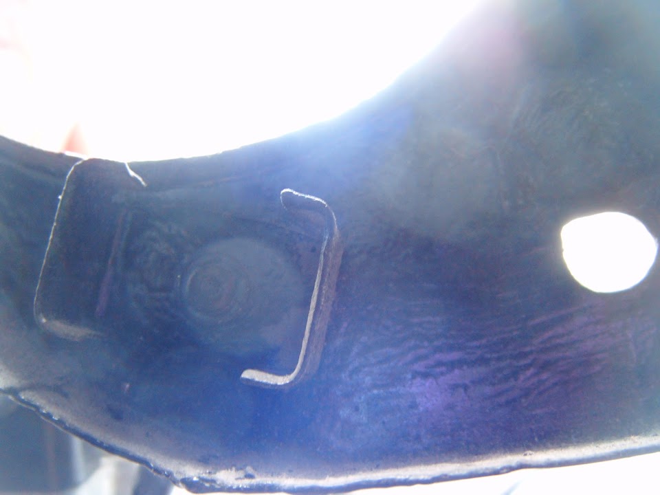
So the covers had to go back on and I came back for another attempt at finishing this off later on.
With the bracket bolted into position, you can see there is a lip in the bracket that sits over the radiator mount.

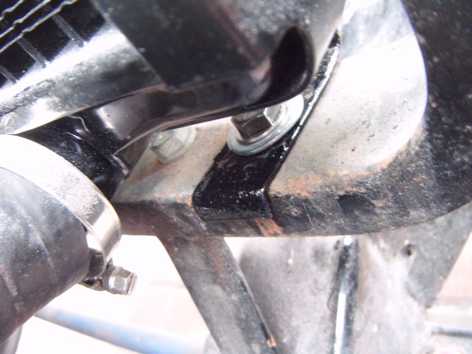
Then I could add the bottle and tighten up the small bolt that holds it in place.

Before swapping out the old pipe for the new one attached to the new, wider radiator.

It had actually starting raining again before I had finished this job.
So I just stayed out and got wet, rather than make 3 attempts at sorting out this simple task.
- - - - - - - - - - - - - - - - - - - - - - - - - - - - - - -
Back indoors I had another look at sealing off the hole for the wiper controls.
Originally, I was going to fix this metal "blank" into position.
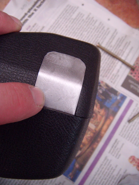
But there is a "lip" on the other half of the steering column cover that was going to get in the way a bit.

So I decided on a change in plans that saw me remove this lip completely from the bottom part of the cover.
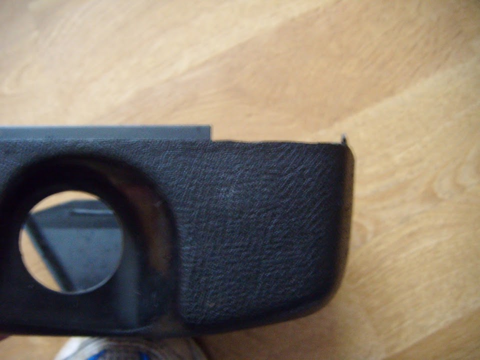
Before simply taping up the hole on the top part of the cover from the outside.
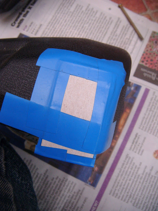
Leaving me with the area to fill in on the inside.
Then I mixed up a very small batch of fibreglass filler to fill in the hole and the surrounding area.

I'm sure this will require a bit of tidying up before I can paint the outside surface black to help it blend in.
- - - - - - - - - - - - - - - - - - - - - - - - - - - - - - -
As it is still lashing down outside as I type this, I'm calling it a day and getting on with some other chores instead.
Take care, Paul.
|
21st September 2015, 16:07
|
|
Senior Member
|
|
Join Date: Apr 2014
Location: Midlands
Posts: 405
|
|
As always Paul I sympathise in your pain, rained stopped play from 9am here so decided I better continue and do some work for my startup business that I am in the process of beginning.
Paul I saw your post on Micks thread, I believe you might be able to retro fit the overdrive onto the steering column with a stalk. It was the same as the MGB I restored that had a switch on the gear stick an but they also on other years had it on a stalk so I just purchased used parts and relocated the wiring. Just an idea
|
22nd September 2015, 15:58
|
|
Senior Member
|
|
Join Date: Feb 2012
Location: Wembley, London
Posts: 5,056
|
|
Jones - Unfortunately, there is nowhere to attach a over drive stalk on my steering column.
I guess I would be able to mount a switch on the dash board, something like this.

That would certainly allow me to fit a gear knob that didn't shout out "Triumph overdrive".
( My mate's old Dolomite 1850 was the first car I saw/drove with this type of gear knob switch. )
Although my car will actually have a number of Triumph touches (steering wheel centre, wheel centres, etc.).
I was even thinking of adding the Triumph motorcycle logo from the bike in my avatar, like AndyP57.

So I might as well leave the gear knob alone, especially given how long my current "To Do" list is.
PS
Good luck with your new business.
- - - - - - - - - - - - - - - - - - - - - - - - - - - - - - -
Plodding Along:
I just couldn't get my free time & the dry weather to line up today, but I still managed to get a few little jobs done, both inside & out...
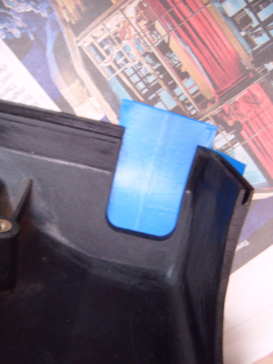
Sanded down the fibreglass filler I had used to "fill in" the wiper lever hole in the steering column cover.
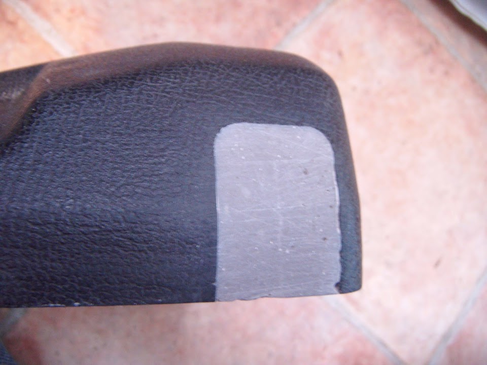
Then masked the whole thing off so I could spray some etch primer over the filler.
Made another cardboard template for the two holes required for the headlight adjustment screws.

Because I had to "fill in" the original ones I drilled many moons ago after the "cut & shut" work on the drivers wing / bonnet.
In order to ensure that my Moon Rover is working OK, I will be temporarily fitting the front headlights & indicators to the bonnet.
This will also allow me to double check the routing of the wiring loom around the front of the chassis too.
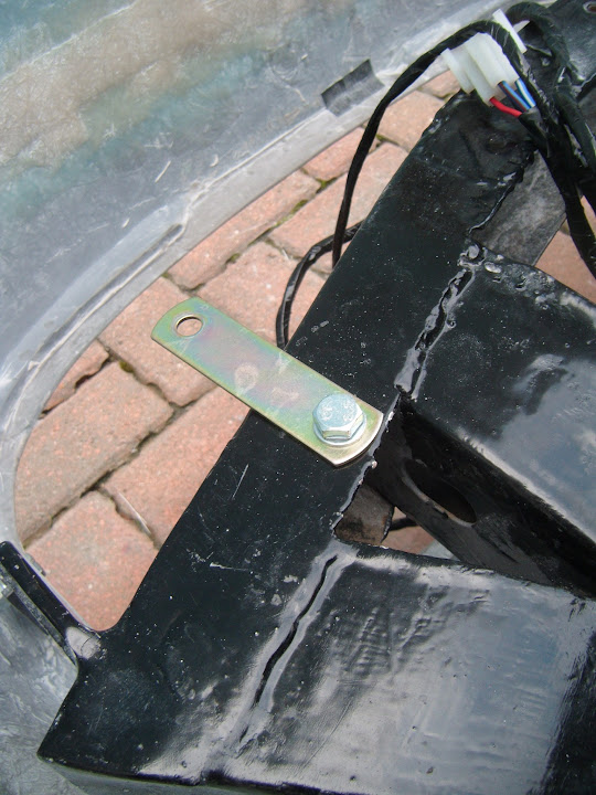
Talking of lighting, I put a coat of stone guard on one side of the rear number plate bracket, although it isn't a great photo.

Later in the day I got a coat on the other side too.

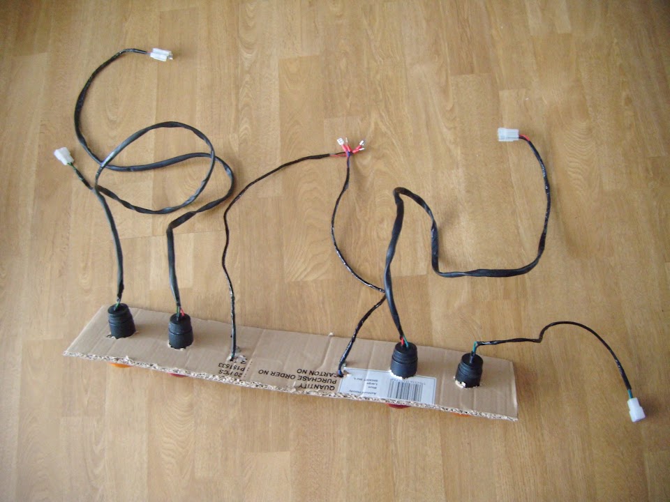
I wired up the temporary lighting board in the boot.

Note: I still need to modify the loom to switch from 3 x LED number plate lights I was planning to fit, to the 1 x bulb lighting I will be using.
Marked up when the headlight adjustment holes needed to be and drilled them out.


Note: I still need to work out the best way of actually fixing the headlights (& the front indicators) to the bonnet.
- - - - - - - - - - - - - - - - - - - - - - - - - - - - - - -
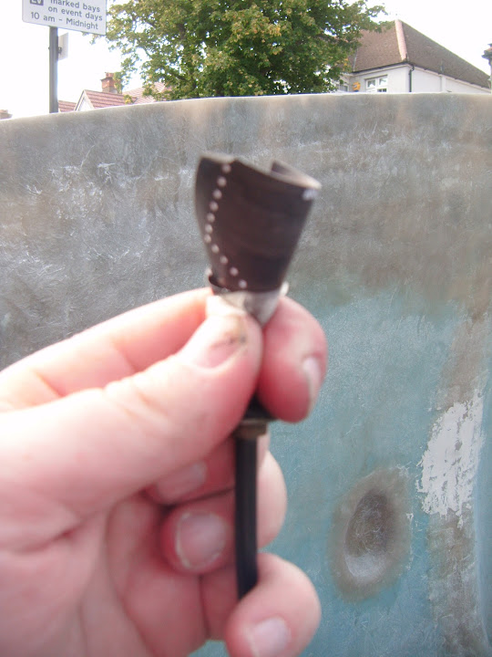
The last of the Mascots:
I am not 100% sure why I became convinced that a bonnet mascot would make a great finishing touch to this build.
I think it was the fact that so many of the people who passed by asked me if it was a Jaguar, that I looked into buying one of these.

Then Ebay being the kind of place it is, I ended up with a small collection of mascots, that need to return to Ebay at some point.

Well today I had a play around with my final mascot option...

Deep down, even though part of me still likes the idea in principle, I know it would be a big mistake to fit one in practise.
Especially after watching those cars racing at the Goodwood revival, as they all looked the part without one.
So I will just go with the plan of painting a yellow band around the nose, and sticking a racing roundel on the bonnet.
- - - - - - - - - - - - - - - - - - - - - - - - - - - - - - -
Until next time, take care, Paul.
|
23rd September 2015, 18:22
|
|
Senior Member
|
|
Join Date: Feb 2012
Location: Wembley, London
Posts: 5,056
|
|
One Of Those Days - Part 1:
It all started off well enough as I got some black paint on the fill in panel on the steering column cover.

I also painted the bottom half of the number plate light bracket on both sides.

- - - - - - - - - - - - - - - - - - - - - - - - - - - - - - -
Then a sign of things to come arrived when I pulled the headlight shells out of their storage box.

Unfortunately, I had completed the wiring for one headlight before threading it through the shell.
So I carefully separated the wires from the block connector...

Only to find that the grommet wouldn't go into place unless threaded from the other side.
I was so annoyed at the fact I had to unpick the block connector at the other end I forgot to take a photo.
Eventually, the wires were secure in the headlight shell and all the connectors were back were they started.

Originally, I was going to use 3 self tapping screws to fit the headlight and had even cut 3 holes in the rubber seal.
Now I have decided to use 4 bolts instead, so I had to sort out the relevant holes in both the shell & the rubber seal.

The next small problem of the day was due to the fact the holes in the bonnet were not quite big enough.
( Due to the way the rubber seal wraps around the shell. )

A bit of filing down later and the shell on the driver's side could be pushed into place, ready to drill the fixing holes.
In order to make sure all the holes were in the right place, I did them one at a time, pushing each bolt into place as I went along.

Eventually, I had all four holes in the bonnet and the headlight shell could be fitted.


Thankfully, the passenger side only required a small bit of filing in a few areas.

Then following the same steps as before, that side was done too.

Note:
By now I had marked each shell, just in case there was any slight variation from one to the other.
For now, I've just tightened up two bolts on each shell, leaving the other two bolts loose.
And this is the view from the front.

- - - - - - - - - - - - - - - - - - - - - - - - - - - - - - -
End of Part 1...
|
|
Currently Active Users Viewing This Thread: 2 (0 members and 2 guests)
|
|
|
| Thread Tools |
|
|
| Display Modes |
 Linear Mode Linear Mode
|
 Posting Rules
|
You may not post new threads
You may not post replies
You may not post attachments
You may not edit your posts
HTML code is Off
|
|
|
All times are GMT +0. The time now is 08:11.
|


