|
|
| Vintage and Classic Roadster Kit Car Builds For Vintage and Classic era kit cars. Post your build reports, problems and progress here |

1st December 2016, 17:47
|
 |
Senior Member
Enthusiast
|
|
Join Date: Mar 2005
Posts: 3,080
|
|
Quote:
Originally Posted by Amir Manzoori

Job well done, as no one could do it better than yours elf.
|
It would be nice to have a few elves in my garage....they could finish my car for me for Christmas!!  |
1st December 2016, 18:05
|
|
Member
|
|
Join Date: Jul 2014
Location: Ealing London
Posts: 54
|
|
 Misspelling
Sorry for the misspelling. The sentence should have ended with YOUR SELF and not yous elf
|
1st December 2016, 21:59
|
|
Senior Member
Enthusiast
|
|
Join Date: Jan 2007
Posts: 932
|
|
Quote:
Originally Posted by peterux
It would be nice to have a few elves in my garage....they could finish my car for me for Christmas!! |
......... and spoil all your fun?!
No, let the elves help Santa and leave you to do what you do best
 |
13th December 2016, 20:40
|
|
Senior Member
Enthusiast
|
|
Join Date: Mar 2005
Posts: 3,080
|
|
 Propshaft tunnel mods
I've been putting off completing the gearbox cover so decided it was best to complete the mods on the propshaft tunnel first.
The Sabre is designed to use the Ford Sierra handbrake and cable. This is mounted to a steel plate mounted above the propshaft tunnel.
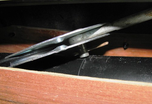
Since the BMW engine and gearbox are mounted higher up to clear the front chassis crossmember the propshaft runs higher in the tunnel and now fouls on the handbrake mechanism.
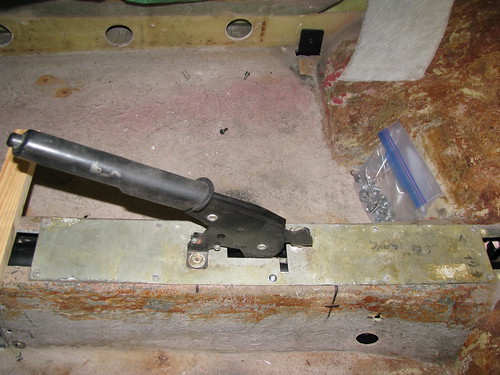 Handbrake Handbrake by Sabrebuilder, on Flickr
Here you can see where the handbrake clevis pin fouls on the propshaft.
 Handbrake Tunnel Mods Handbrake Tunnel Mods by Sabrebuilder, on Flickr
I tried raising the handbrake by putting 20mm square section ali tube between the tunnel top and the handbrake mounting plate but the handbrake cable half moon bracket fouled on the top of the tunnel. So I decided to cut the top of the propshaft tunnel of with a slitting disc in my angle grinder to allow me to raise it by 20mm.
 Handbrake Tunnel Mods Handbrake Tunnel Mods by Sabrebuilder, on Flickr
I then prepared two strips of 3mm plywood to temporarily hold the tunnel tops raised by 20mm. Here is the plywood strip fixed with self tappers on the passenger side.
 Handbrake Tunnel Mods Handbrake Tunnel Mods by Sabrebuilder, on Flickr
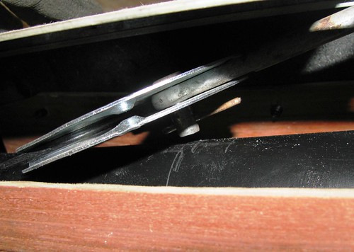
With the passenger side tunnel top fixed and the handbrake refitted I could now see the problem better from the drivers side. Despite raising the top of the tunnel by 20mm, the clevis pin was still resting on the propshaft.
 Handbrake Tunnel Mods Handbrake Tunnel Mods by Sabrebuilder, on Flickr
I didn't want to raise the tunnel anymore but realised I could raise the handbrake on its mounting plate without the puller rod fouling on the plate, so I cut and fitted two 10mm spacers.
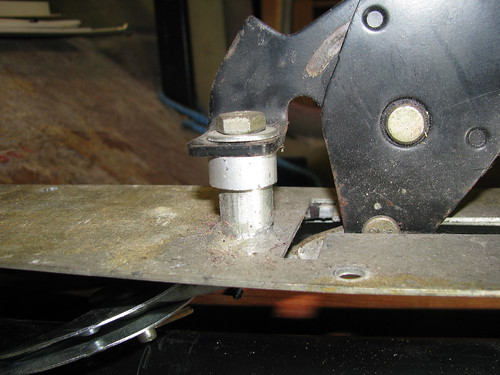 Handbrake Tunnel Mods Handbrake Tunnel Mods by Sabrebuilder, on Flickr
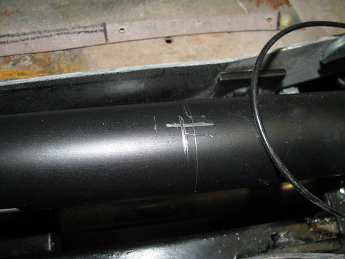
With the tunnel raised and the spacers fitted the clevis pin was just clearing the propshaft but still a bit close. The clevis pin is not a standard Ford part and was fitted by the original builder.
 Handbrake Tunnel Mods Handbrake Tunnel Mods by Sabrebuilder, on Flickr
I cut the clevis pin down and re-drilled another hole making it a better fit. I plan to replace the old split pin with an 'R' clip or maybe try to source an original Ford pin with a circlip. This picture shows the clearance with the handbrake in the off position. It's even better with the handbrake pulled on.
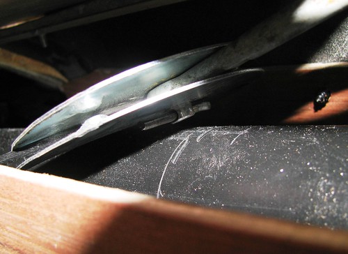 Handbrake Tunnel Mods Handbrake Tunnel Mods by Sabrebuilder, on Flickr
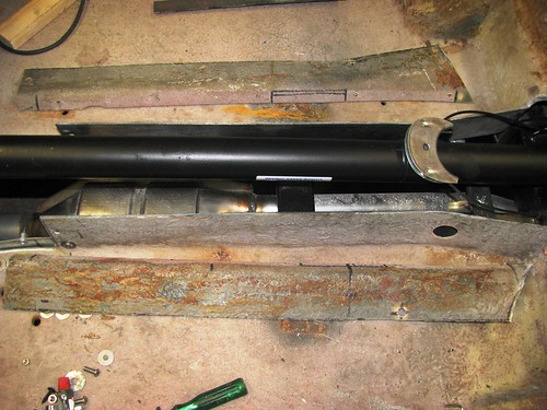
Here's the handbrake and tunnel fixed with the plywood former on the drivers side.
 Handbrake Tunnel Mods Handbrake Tunnel Mods by Sabrebuilder, on Flickr
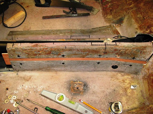
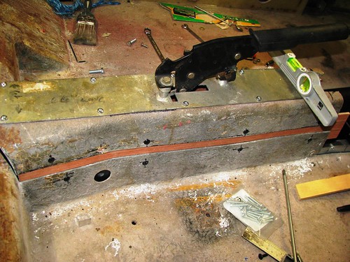
I then dismantled it all and cleaned up the surfaces of the tunnel with a flap wheel in the angle grinder. Then re-assembled with brown packing tape applied to the plywood to stop the fibreglass sticking to the plywood formers.
I've filled the gaps with P40 GRP filler. I will then overlay both sides with a few layers of GRP to restore the original strength of the tunnel.
 Handbrake Tunnel Mods Handbrake Tunnel Mods by Sabrebuilder, on Flickr
When the the tunnel is finished and in its final position I can then move on and tackle the gearbox cover.
...peter

|
26th January 2017, 09:26
|
|
Senior Member
Enthusiast
|
|
Join Date: Mar 2005
Posts: 3,080
|
|
Well with Christmas and New Year celebrations over and all the decs put away it was time to get back in the garage before spring arrives and other outdoor projects become a priority again.
It's been b***dy cold in this part of the country and my garage is old detached and often colder inside than outside.
I thought I would tackle the wiring of the dashboard thinking that would be something I could do indoors but all the preparation work has been outside in the cold....
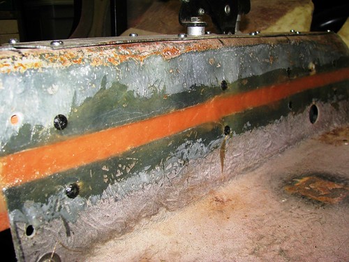
The Sabre I bought had the dashboard surround covered in cream coloured leather by a professional upholsterer in about 1995. The leather covering was very dirty after 22 years of neglect! My original plan was to rip it off and start again but I thought I'd have a go at restoring it first. I tried various cleaners but the most effective was Vanish carpet cleaner. It's come up quite well but some small scuffs will need to be treated.
 Dashboard surround - before Dashboard surround - before by Sabrebuilder, on Flickr
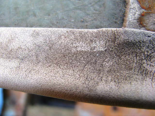
And after cleaning....
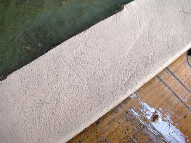 Dashboard surround - after Dashboard surround - after by Sabrebuilder, on Flickr
The dashboard surround is mounted by this central bracket that bolts to the scuttle frame plus a 'z shaped' bracket at each end. The central bracket clashed with one of the warning lamp holes already pre-cut in my dashboard, so I had to mount it slightly rotated.
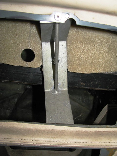 Dashboard Surround mounting Dashboard Surround mounting by Sabrebuilder, on Flickr
I'm using a Ford Sierra fan motor switch. I had to make a metal plate to mount the switch behind the GRP dashboard surround. These little jobs can be very time consuming!
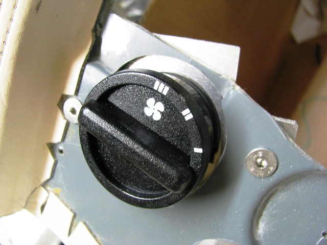 Heater Fan Switch Heater Fan Switch by Sabrebuilder, on Flickr
I couldn't find any warning lights that I liked so I made these out of two different lamps. The bodies are LED indicators from Hong Kong and the lens was cut of the top of a Europaspares lamp. The lens was lapped flat and then carefully bond to the body with clear silicone sealer.
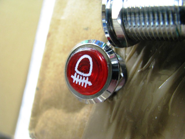 LED Warning Lamps LED Warning Lamps by Sabrebuilder, on Flickr
And finally for this update, Durite period looking fog light switches mounted in the 'IVA dashboard exempt zone' (hopefully!).
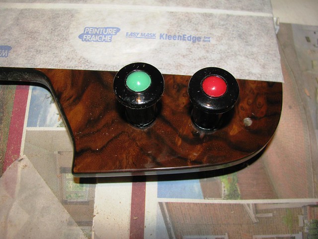 Front and rear fog light switch Front and rear fog light switch by Sabrebuilder, on Flickr
More to follow next week.....
....peter
|
14th April 2017, 19:09
|
|
Senior Member
Enthusiast
|
|
Join Date: Mar 2005
Posts: 3,080
|
|
Quote:
Originally Posted by peterux
I had already bought a pair of Mk1 MX5 seats but they don't have the shoulder high seat belt supports. My Sabre chassis has rather low seat belt mounting positions that would fail the IVA regulations. The Mk3 MX5 seats have seat belt supports that raise the turning point. I believe the IVA will accept this as a solution as long as the seats are designed to take the forces.
 Mazda MX5 Mk3 seats Mazda MX5 Mk3 seats by marlinpeter, on Flickr
....peter |
Having further looked into the IVA rules for using seats with built-in seat belt supports I have decided against them. To use these seats I would need to have structurally strong base supports welded to the chassis rails. I now think it will be much easier to raise the original shoulder height supports and use the Mk 1 seats.
On the upside, I bought these seats for £50 and sold them for £155  |
15th May 2017, 19:30
|
|
Senior Member
Enthusiast
|
|
Join Date: Mar 2005
Posts: 3,080
|
|
Sorry for the lack of updates but I've been busy with other projects for most of the winter and spring. The only real progress has been reconstructing the gearbox tunnel to fit around the BMW gearbox which has actually taken more time than I would have liked but I'm nearing completion now.
It's not terribly exciting so I'll mostly let the pictures tell the story....
(you can click on any of the photo's for more details )
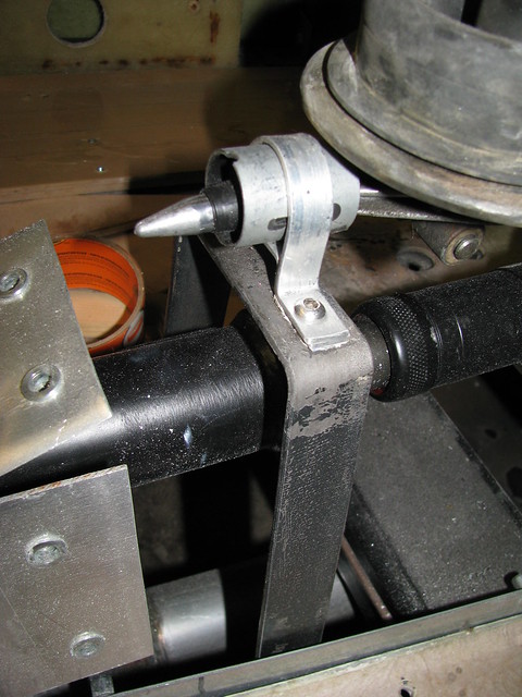 Gear change support Gear change support by Sabrebuilder, on Flickr
 Gearbox Tunnel mods Gearbox Tunnel mods by Sabrebuilder, on Flickr
 Gearbox Tunnel Mods Gearbox Tunnel Mods by Sabrebuilder, on Flickr
 Gearbox Tunnel Mods Gearbox Tunnel Mods by Sabrebuilder, on Flickr
 Gearbox Tunnel Mods Gearbox Tunnel Mods by Sabrebuilder, on Flickr
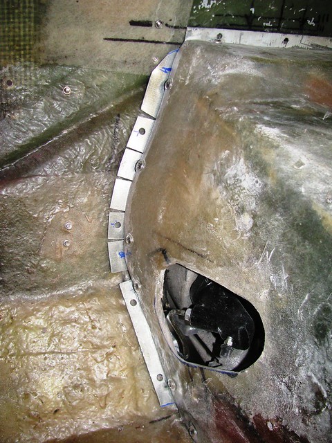
Steel flange added to left-hand side. All flanges are spaced off the bulkhead by about 3mm. The gap will be filled with Neoprene foam sealing strip.
 Gearbox Tunnel Mods Gearbox Tunnel Mods by Sabrebuilder, on Flickr
 Gearbox Tunnel Mods Gearbox Tunnel Mods by Sabrebuilder, on Flickr
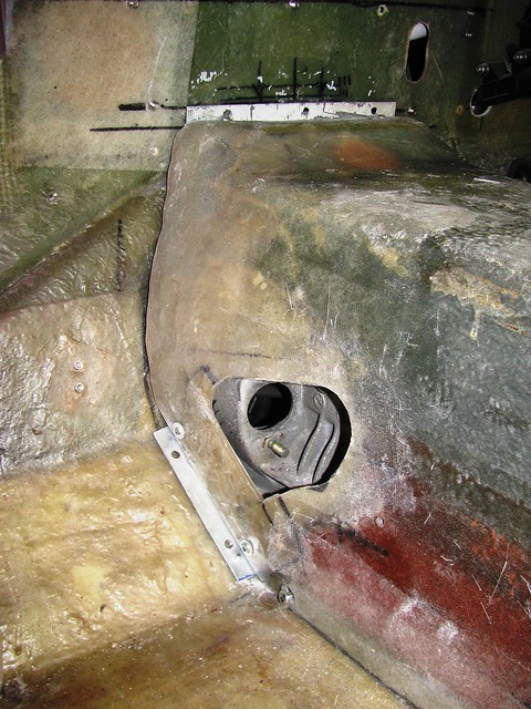
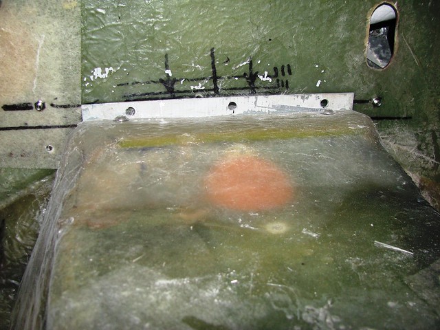
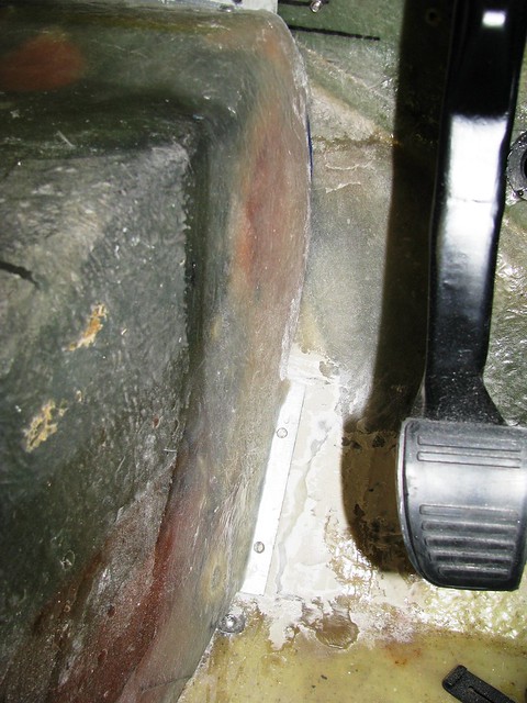
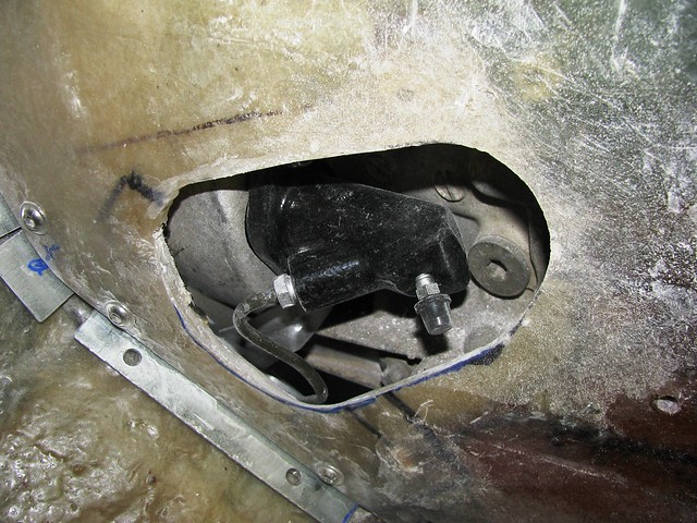
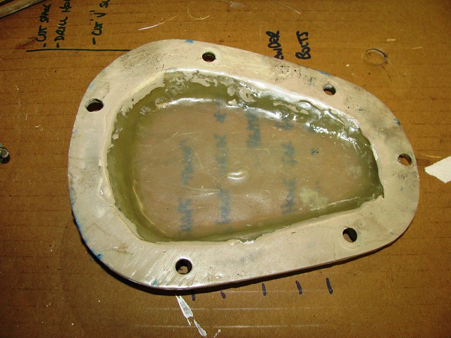
I needed to make a small access panel to go over the clutch slave cylinder which is accessed through a hole in the side of the gearbox tunnel. The clutch hydraulic pipe is slightly proud of the tunnel side so the cover needed to be raised. I made this mould out of artists foam board and packing tape. (This picture was taken after the mould had been used.)
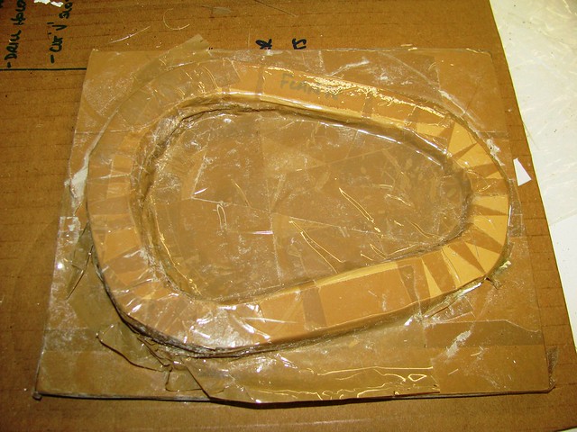 Clutch Slave cylinder gearbox tunnel cover Clutch Slave cylinder gearbox tunnel cover by Sabrebuilder, on Flickr
 Clutch Slave cylinder gearbox tunnel cover Clutch Slave cylinder gearbox tunnel cover by Sabrebuilder, on Flickr
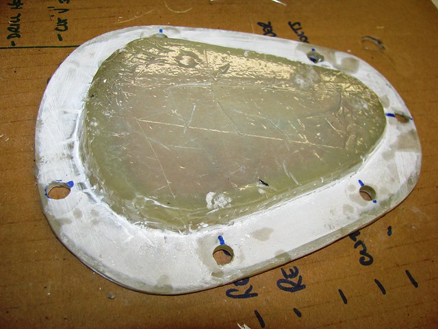 Clutch Slave cylinder gearbox tunnel cover Clutch Slave cylinder gearbox tunnel cover by Sabrebuilder, on Flickr
I used m6 flanged screws and nutserts (rivnuts) to fix it to the tunnel. I will probably seal around the flange with RTV silicone when the car is finished. The panel will be hidden by the carpet and underlay.
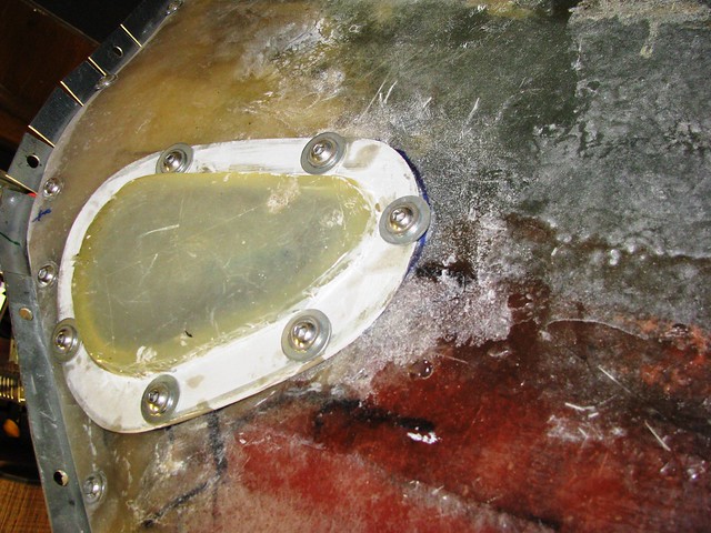 Clutch Slave cylinder gearbox tunnel cover Clutch Slave cylinder gearbox tunnel cover by Sabrebuilder, on Flickr
Next update will follow when time permits.... 
|
24th June 2017, 20:20
|
|
Senior Member
Enthusiast
|
|
Join Date: Mar 2005
Posts: 3,080
|
|
Time for a small update from the last few weeks....
I had an issue with the original donor car's front hubs that came with my kit. They had a lot of play in the bearings and changing the bearings (twice!) made no improvement. My conclusion is that the hub casings had become oval through accident damage. My Sabre kit was started in 1994 and the donor Sierra was registered in 1992 supporting the hypothesis that it was an accident damaged donor. I have bought some brand new hubs that are not genuine Ford parts but have been manufactured using Ford tooling.
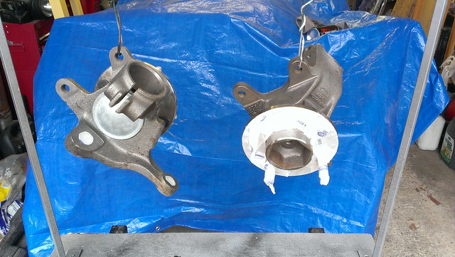 New front hubs 1 New front hubs 1 by Sabrebuilder, on Flickr
They were then given three coats of chassis black to prevent rusting...(which at my rate of build is quite likely!!)
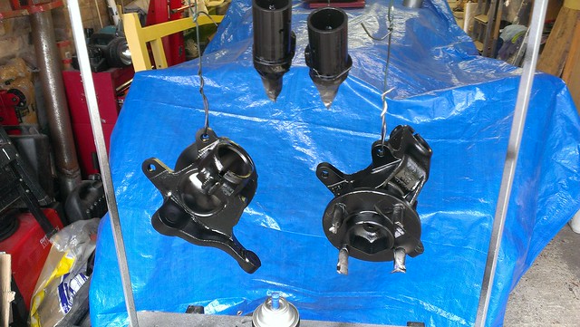 New front hubs 2 New front hubs 2 by Sabrebuilder, on Flickr
And here they are fitted...
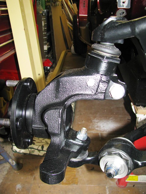 New Front Hubs New Front Hubs by Sabrebuilder, on Flickr
The front hubs and ball joint adaptors were drilled to take an m6 retaining bolt. This is to prevent the adaptor coming out of the hub if the m10 fixing bolt should become loose. This is an IVA requirement.
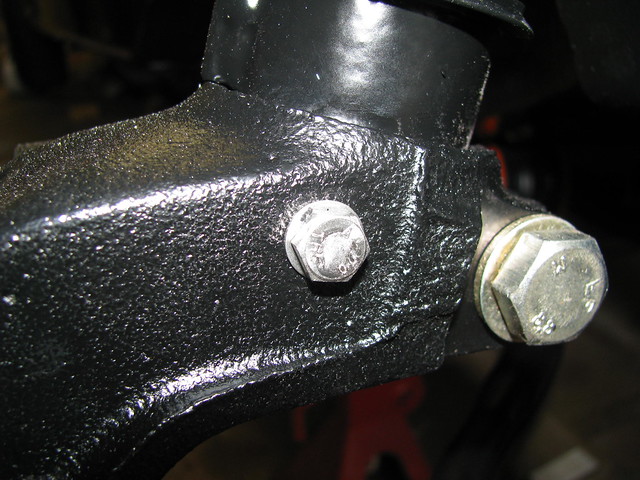 Front HUB - IVA fix Front HUB - IVA fix by Sabrebuilder, on Flickr
I've reverted back to the original design of the ARB rubber bushes as recommended by Ford. Ford issued a Technical Bulletin stating that the so called Heavy Duty bushes should not be used. According to Ford the original bushes were designed to distort and change the suspension geometry under heavy braking. ( I have also fitted some nice looking stainless steel washers available on ebay.)
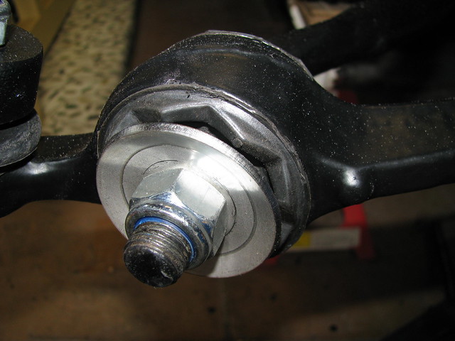 ARB bushes and washers ARB bushes and washers by Sabrebuilder, on Flickr
I noticed that when I stripped down the suspension the original silicon grease had dried out and the bushes and ARB were stiff, so during re-assembly I used this PTFE loaded silicone grease.
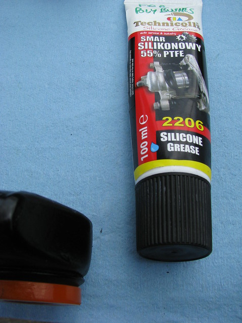 Polybush grease Polybush grease by Sabrebuilder, on Flickr
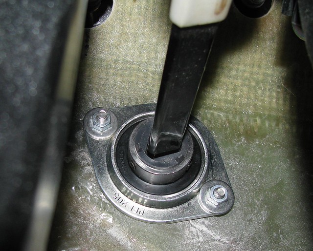
It is a well documented upgrade on Ford based kit cars (and TVRs) to replace the Ford plastic steering column bush with a 'proper' bearing. This pressed steel housed bearing from Simply Bearings is commonly used.
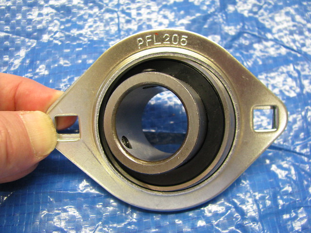 Steering column bearing Steering column bearing by Sabrebuilder, on Flickr
The first step is to fit the triangular plastic part from the Ford bush to the bearing and fix it in place with the two grub screws.
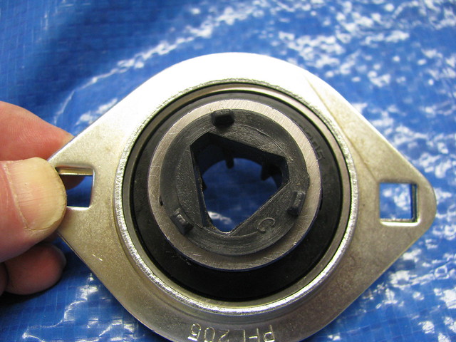 Steering column bearing Steering column bearing by Sabrebuilder, on Flickr
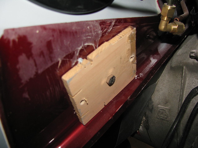
I needed to open up the bush hole in the body to match the new bearing. I made up this alignment tool made from a scrap of mdf and a socket the same diameter of the existing hole.
 Steering column bearing Steering column bearing by Sabrebuilder, on Flickr
The alignment tool was first inserted in the existing hole and the two mounting holes where drilled through the bulkhead.
 Steering column bearing Steering column bearing by Sabrebuilder, on Flickr
The MDF template was then bolted to the inside of the bulkhead
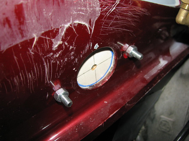 Steering column bearing Steering column bearing by Sabrebuilder, on Flickr
I then used a hole saw to cut the larger hole concentric with the original.
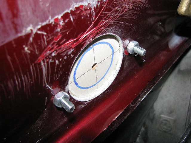 Steering column bearing Steering column bearing by Sabrebuilder, on Flickr
Bearing mounted loosely initially to allow the bearing to take up its natural angle.
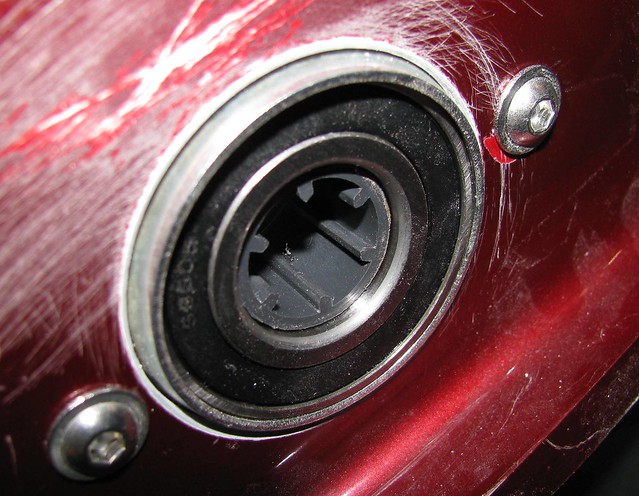 Steering column bearing Steering column bearing by Sabrebuilder, on Flickr
New bearing from inside the car. Nylock nuts will be used on final assembly.
 Steering column bearing Steering column bearing by Sabrebuilder, on Flickr
Next on the list is to finalise the steering column and couplings.......
....peter
|
15th July 2017, 22:02
|
|
Senior Member
Enthusiast
|
|
Join Date: Mar 2005
Posts: 3,080
|
|
Steering
When I first got the Sabre it was fitted with a Sierra manual steering rack and column extension pieces.
I decided to fit a Granada power steering rack and what I think is the relevant extension piece. When I assembled all this for the first time I was worried that the lower column extension does not align with the steering rack pinion which puts a lot of strain on the rubber isolator. However, looking at another Sabre at the Stoneleigh kitcar show I confirmed that I have the right parts and they are assembled in the right way. The other Sabre also demonstrates this alignment issue suggesting that this is a common problem with the power steering rack. I thought a better alignment could be achieved by re-positioning the fixed midway bearing so I eventually got round to fixing this.
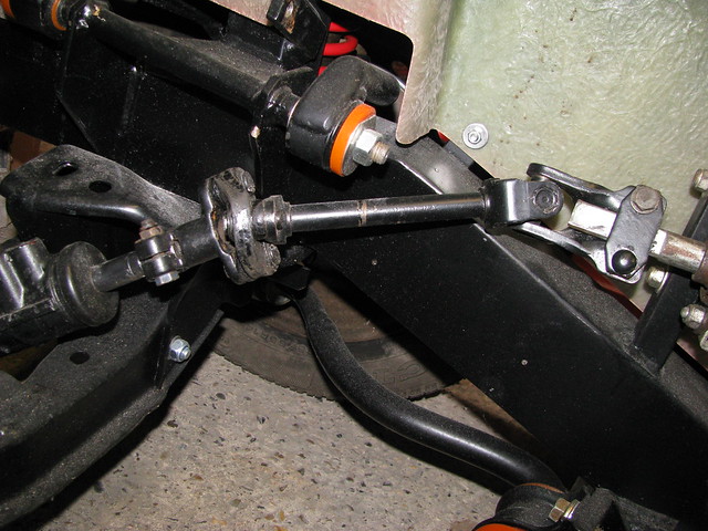 Steering column alingment Steering column alingment by Sabrebuilder, on Flickr
I have re-positioned the bearing upward and inwards towards the engine so that the lower steering coupling is aligned to the input shaft of the steering rack. The upper steering shaft now runs parallel to the chassis rail and approx. horizontal.
 Steering intermediate bearing Steering intermediate bearing by Sabrebuilder, on Flickr
The lower coupling is now aligned with the input shaft to the power steering rack. This means that there is no additional strain on the rubber disc.
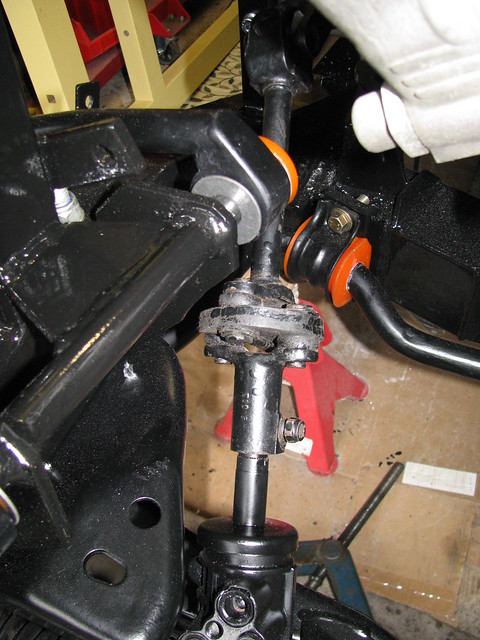 Lower Steering coupling Lower Steering coupling by Sabrebuilder, on Flickr
Rear side of bearing showing details of the extension plate. Not very pretty but functional and very solid.The plate will be painted and fitted with nylocks.
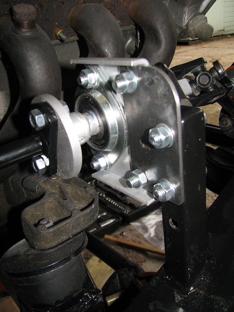 Steering intermediate bearing Steering intermediate bearing by Sabrebuilder, on Flickr
next job is the power assisted steering hoses.......
...peter
Last edited by peterux; 15th July 2017 at 22:03..
Reason: grammer
|
25th July 2017, 19:28
|
|
Senior Member
Enthusiast
|
|
Join Date: Mar 2005
Posts: 3,080
|
|
Power Assisted Steering
I plan to use a Ford Granada steering rack driven by the BMW PAS pump (because it came with the BMW engine). The BMW pump is conveniently marked with 110 bar output pressure but I struggled to find the spec for the comparable Ford pump.
I eventually found a very helpful Steering Rack specialist company (Western Power Steering) who confirmed that the original pump would have been rated at about 90 bar, but it is the nominal flow that is more important and both pumps would be similar and the BMW pump would be more than capable of working the rack.
I guess time will tell when I get to drive the car!
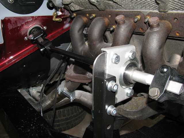
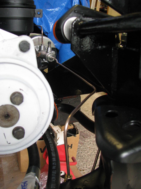
First, I temporarily refitted the BMW Power assisted steering pump(still in primer) to work out routing of the high pressure lines.
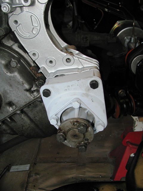 Power Steering pump Power Steering pump by Sabrebuilder, on Flickr
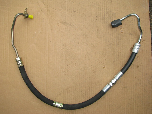
To connect the Ford Granada steering rack to the BMW steering pump I started with a new Ford high pressure hose and a BMW hose.
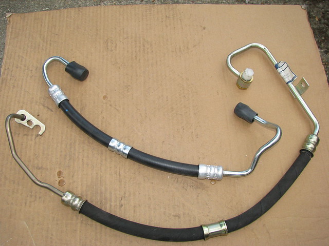 Power Assisted Steering Hose Power Assisted Steering Hose by Sabrebuilder, on Flickr
I then cut the pump end off both pipes ensuring that I kept the Ford restrictor fitted in the middle of the Ford pipe. Both ends were slightly reformed to exit at the right directions. I used the BMW rack end as it suited my solution better than the pump end.
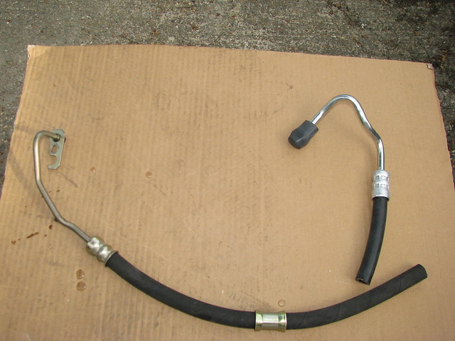 Power Assisted Steering Hose Power Assisted Steering Hose by Sabrebuilder, on Flickr
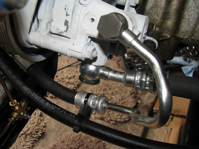
I then visited Hydraulic Components and Systems Ltd in Hemel Hempstead who crimped on a fitting to join the two pipes together. Cost me £20 and they fitted it while I waited. HCS advised that the 'cone' connector is good for an incredible 450 bar so should adequately handle the 110 bar from the BMW pump.
 Power Assisted Steering Hose Power Assisted Steering Hose by Sabrebuilder, on Flickr
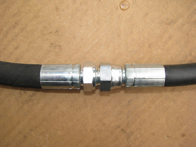 Power Assisted Steering Hose Power Assisted Steering Hose by Sabrebuilder, on Flickr
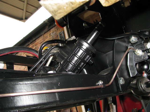
Supply and return hoses supported by front chassis cross rail.
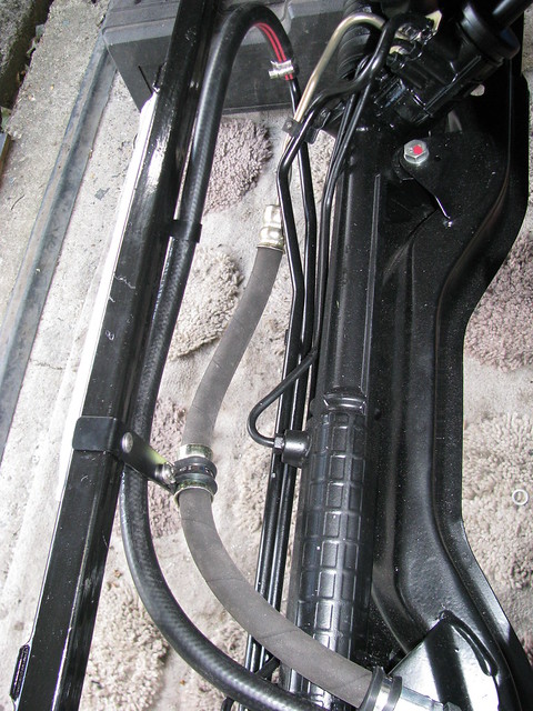 PAS hoses PAS hoses by Sabrebuilder, on Flickr
I made a small support bracket that utilises one of the steering rack mounting bolts.
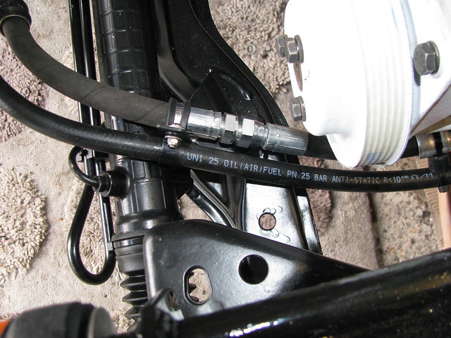 PAS hose support bracket PAS hose support bracket by Sabrebuilder, on Flickr
I'm using the BMW PAS reservoir. (Mounting cradle will be painted.)
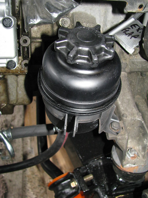 PAS Reservoir PAS Reservoir by Sabrebuilder, on Flickr
I've also bought a new 'reservoir to pump' hose. New crush washers to be fitted on final assembly.
 PAS hoses PAS hoses by Sabrebuilder, on Flickr
Can't wait to see if all works!! 
So another job ticked off the list..........
Next up will be fitting the front brakes and pipes.......
...peter
|
25th July 2017, 20:36
|
 |
Senior Member
Enthusiast
|
|
Join Date: Feb 2005
Location: Hampshire
Posts: 2,497
|
|
Nice work |
2nd August 2017, 20:38
|
|
Senior Member
Enthusiast
|
|
Join Date: Mar 2005
Posts: 3,080
|
|
Front Brakes
Quote:
Originally Posted by Patrick
Nice work |
Thanks, Patrick.
--------------------------------------------------------------------------------------
Having rebuilt the front suspension and sorted the PAS steering, I could now move on the fitting the front brakes.
I started by installing the brake discs and the calipers that I re-furbished back in the winter. The discs were new when I bought them but it's been so long ago they have a bit of surface rust.
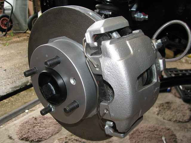 Brake disc and caliper Brake disc and caliper by Sabrebuilder, on Flickr
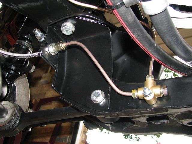
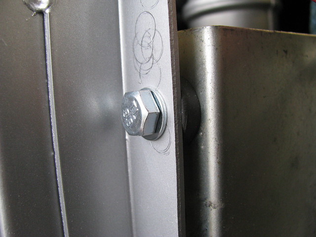
I'm using Goodridge flexible hoses but the front hoses have the wrong size fitting for the Ford crossbeam mounting point. I tried using a nut each side of the mounting but that made it too short for the pipe fitting the other side. So I made up a stainless steel hexagon shaped washer which worked a treat.
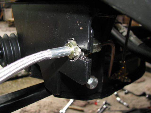 Front Brake Flex hose Front Brake Flex hose by Sabrebuilder, on Flickr
I've mounted the front tee fitting on the front crossbeam.
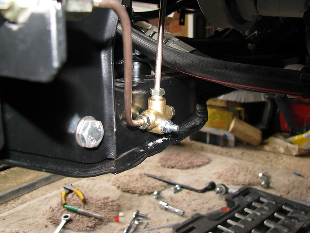 Front Brake pipes Front Brake pipes by Sabrebuilder, on Flickr
Brake pipe will be p-clipped to the chassis rail when I have the engine out for painting.
 Front Brake pipes Front Brake pipes by Sabrebuilder, on Flickr
Technically speaking, once this pipe is p-clipped to the chassis rail, the IVA requirement of fixings every 30 cm would be met but the brake pipe did look a little vulnerable so I made up an additional support tab.
 Front brake pipe support Front brake pipe support by Sabrebuilder, on Flickr
Tee fitting to offside brake flexi.
 Front Brake pipes Front Brake pipes by Sabrebuilder, on Flickr
..........to the nearside brake caliper.
 Front Brake pipe Front Brake pipe by Sabrebuilder, on Flickr
So that's the complete Brake System finally completed awaiting bleeding after the final body tub fitting.
Next up will be the cooling system........
...peter
|
2nd August 2017, 21:02
|
|
Member
|
|
Join Date: Oct 2015
Posts: 83
|
|
Great work , can I ask were you able to use existing holes for your T fittings and P clips ?
My vehicle is a simple rebody so no IVA.
|
3rd August 2017, 20:12
|
|
Senior Member
Enthusiast
|
|
Join Date: Mar 2005
Posts: 3,080
|
|
Quote:
Originally Posted by paul_n
Great work , can I ask were you able to use existing holes for your T fittings and P clips ?.
|
Thanks for the feedback, Paul.
No, these pipes take a different routing to the original build so all the holes were newly drilled. |
26th October 2017, 07:27
|
|
Senior Member
Enthusiast
|
|
Join Date: Mar 2005
Posts: 3,080
|
|
Cooling
Well, I've been a little remiss in not updating my diary so i'll try and catch up over the next few days.
First 'catch-up' update is about the cooling system which I tackled back in August.
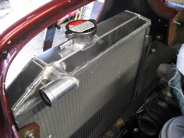
I'm using an alloy radiator designed for a Ford Escort RS2000 Mk2. It's the same size as the one I used in my Marlin Sportster so i know it works well with the BMW engine.
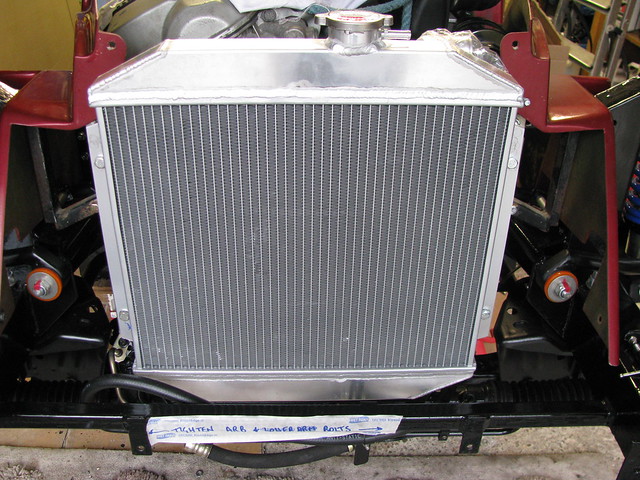 Radiator Radiator by Sabrebuilder, on Flickr
The Escort radiator fits remarkably well behind the Sabre's nose.
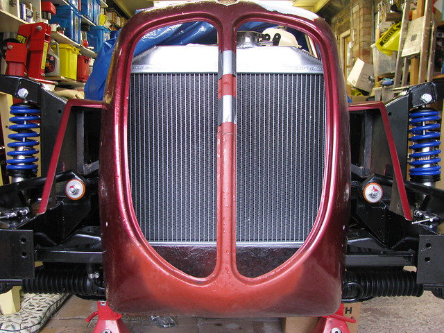 Radiator positioning Radiator positioning by Sabrebuilder, on Flickr
Because I'm fitting a straight 6 BMW engine I had to move the radiator support frame forward by about 65mm. The support frame and brackets are standard parts supplied by Royale. I've put spacer tubes between the radiator support frame and the original chassis mounting tabs. Further strengthening tabs were be fitted but not shown here.
 Radiator Frame spacers Radiator Frame spacers by Sabrebuilder, on Flickr
After extensive internet searching I eventually found these really neat grommets on ebay.
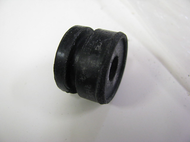 Radiator mounting grommet Radiator mounting grommet by Sabrebuilder, on Flickr
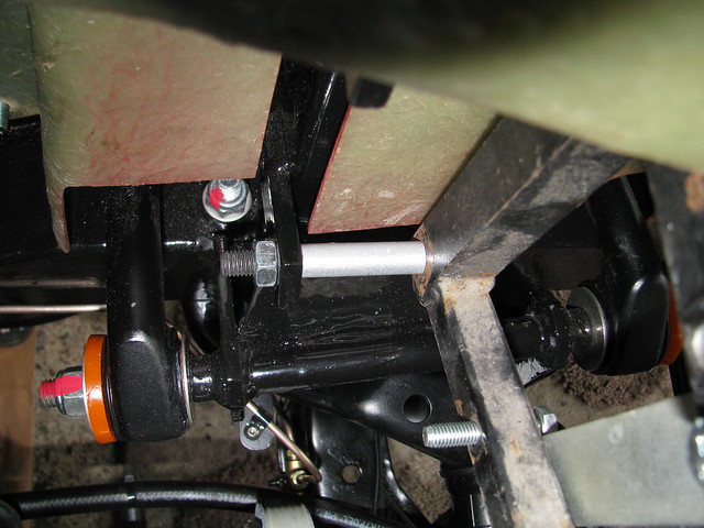
M8 bolt through rubber grommet.
 Radiator mounting Radiator mounting by Sabrebuilder, on Flickr
Despite mounting the radiator much further forward than John Barlow designed it's still possible to reach and remove the radiator cap.
 Radiator clearance. Radiator clearance. by Sabrebuilder, on Flickr
13" Comex fan, supplied by Revotec, mounted on the back of the radiator.
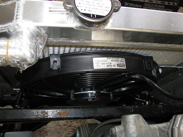 Radiator Fan Radiator Fan by Sabrebuilder, on Flickr
Previously I've used those plastic tie wrap type mounts which damage the radiator so this time I used the Revotec supplied mounting brackets.
 Radiator Fan Radiator Fan by Sabrebuilder, on Flickr
I've chosen this MG Rover 25 ZR coolant header tank (PCF000161). Here I'm lining it up to check clearance with the engine and bonnet top represented by the piece of wood. (You can tell it's summer as I've got my jumper and gloves on :-) )
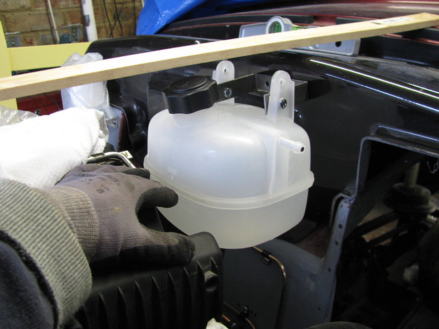 Coolant Header Tank Coolant Header Tank by Sabrebuilder, on Flickr
And that's about as far as I got with the cooling system. Pipework etc will be completed on the final assembly following painting and fitting of the central body tub.
That's all for now, more updates to follow soon.....
...peter
|
30th October 2017, 20:30
|
|
Senior Member
Enthusiast
|
|
Join Date: Mar 2005
Posts: 3,080
|
|
Engine removal trial.
Here's the second of my summer 'catch-up' updates to bring my diary up to date.....
Next up was to remove the engine for a partial recondition and spruce up.
I wanted to see if it was possible to remove the BMW from the Sabre without removing the central body tub. Once the car is finished it would be a huge amount of work to remove the body so I wanted to make sure it is possible to remove the engine should the need arise.
Firstly, I removed the radiator, exhaust manifolds, handbrake, propshaft, clutch slave cylinder, gearbox support, gearbox leaver, etc.
I decided to leave the gearbox bolted to the engine although for something like a clutch change it would be possible to drop the gearbox on it's own.
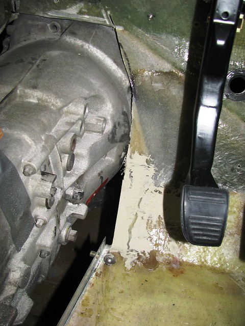
With the engine at the right angle the sump just clears the chassis with the clutch pipe on the bulkhead still in place. It was a very tight squeeze and removing the clutch pipe would have been safer. I did not need to remove the brake master, steering column or the servo.
 Engine Removal Trial Engine Removal Trial by Sabrebuilder, on Flickr
My unconventional BMW engine installation means that the sump sits behind the chassis cross member.
In this shot you can see the sump just clears the chassis with the engine and gearbox at an extreme angle.
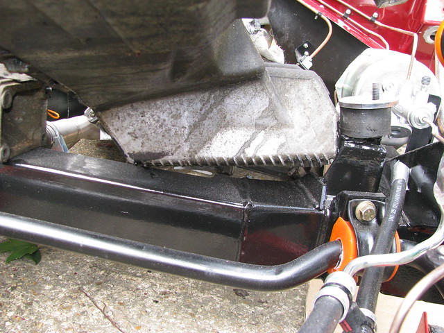 Engine Removal Trial Engine Removal Trial by Sabrebuilder, on Flickr
The sump just cleared the offside engine mounting turret.
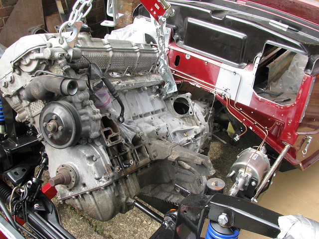 Engine Removal Trial Engine Removal Trial by Sabrebuilder, on Flickr
 Engine Removal Trial Engine Removal Trial by Sabrebuilder, on Flickr
 Engine Removal Trial Engine Removal Trial by Sabrebuilder, on Flickr
 Engine Removal Trial Engine Removal Trial by Sabrebuilder, on Flickr
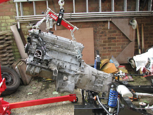
The trial was a success and the engine is out! Of course, my wings nose and bonnet are not fitted but I am now confident that the engine and gearbox can be removed with the wings and body tub still in place.
The engine and gearbox were then separated and the engine mounted on my engine stand for refurbishment.
More on that in the next few days....
....peter
|
5th November 2017, 16:39
|
|
Senior Member
Enthusiast
|
|
Join Date: Mar 2005
Posts: 3,080
|
|
Hunt the rattle.....
Ok, so here comes the third of my 'catch-up' updates......
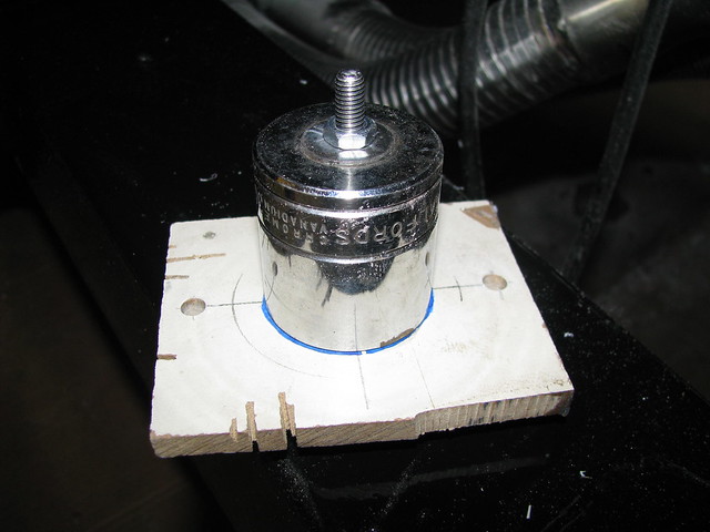
I'm stripping down some of the engine for inspection and some refurbishment. One thing I'm looking for is the source of a rattle on first start up. I suspect worn chain tensioners......First job is to loosen the crankshaft hub bolt and then set the crank at TDC. The hub bolt put up a real good fight but I won!
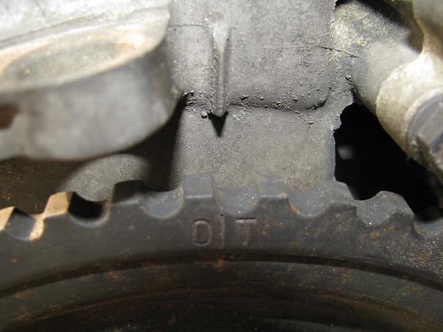 Engine strip and Inspection Engine strip and Inspection by Sabrebuilder, on Flickr
I then fitted my home made camshaft locking tool. The dimensions are in the Haynes manual.
 Engine strip and Inspection Engine strip and Inspection by Sabrebuilder, on Flickr
I take lots and lots of photo's for reference to make sure everything goes back again correctly. Here is an example...
 Engine strip and Inspection Engine strip and Inspection by Sabrebuilder, on Flickr
I was surprised to find that the water pump had a stainless steel impeller. No sign of any BMW logo so I presume the water pump had already been replaced at some time in the engine's life. I had already sourced the new pump shown on the left, so that will be fitted.
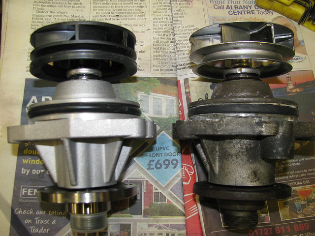 Engine strip and Inspection Engine strip and Inspection by Sabrebuilder, on Flickr
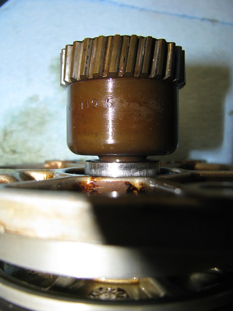
Next I removed the single VANOS unit. Photographed after some cleaning.
 Engine strip and Inspection Engine strip and Inspection by Sabrebuilder, on Flickr
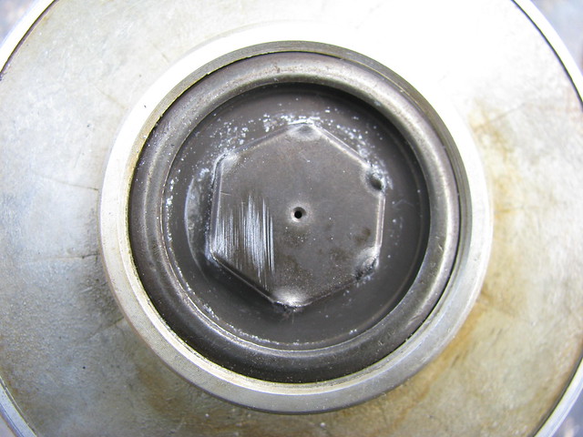
After removing the five screws it was immediately clear that the Vanos piston seal had failed as the piston was loose in the cavity.
 Engine strip and Inspection Engine strip and Inspection by Sabrebuilder, on Flickr
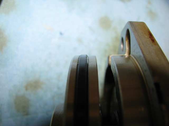
It was also apparent that there is axial play with a notable 'clack' sound when the helical gear is pushed and pulled.
 Engine strip and Inspection Engine strip and Inspection by Sabrebuilder, on Flickr
These are two common failure modes on the BMW M52 engines. These are fully described on the Beisan Systems website here....
http://www.beisansystems.com/
Despite all the warnings I managed to mess up the Vanos piston cap screw. I had to revert to welding a nut on top to get it undone.
 Vanos repair Vanos repair by Sabrebuilder, on Flickr
I bought a Vanos repair kit from VANOS-BMW.com. I was a little wary as they are based in Moscow but the parts are very high quality, well packaged and arrived safely. Teflon and Viton piston o-rings, new bearing ring and piston cap screw. The bearing ring was a perfect fit first time and didn't require any lapping. The kit cost £58 inc delivery and payment is by paypal.
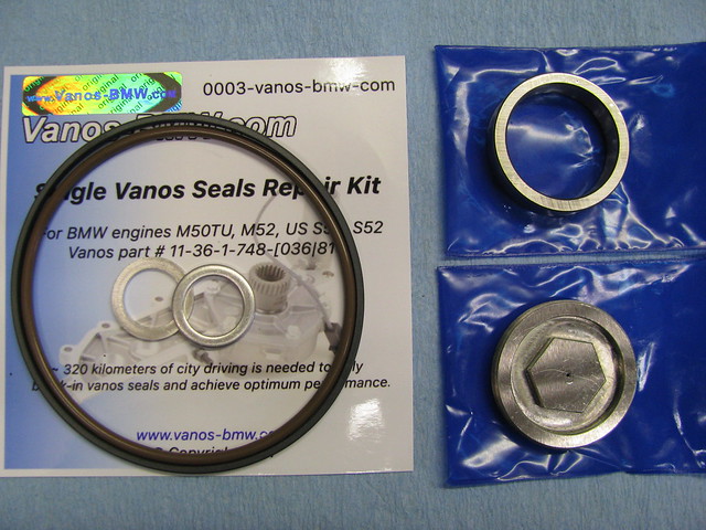 Vanos repair Vanos repair by Sabrebuilder, on Flickr
The new piston cap screw has a 17mm profile that is deeper than than the original BMW part. This part is not available from BMW as they don't expect anyone to service the Vanos unit.
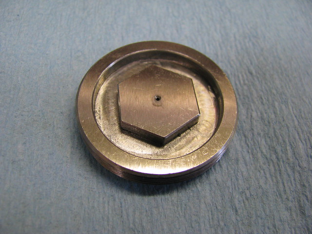 Vanos repair Vanos repair by Sabrebuilder, on Flickr
New Viton and Teflon rings fitted and are now a snug fit in the Vanos body.
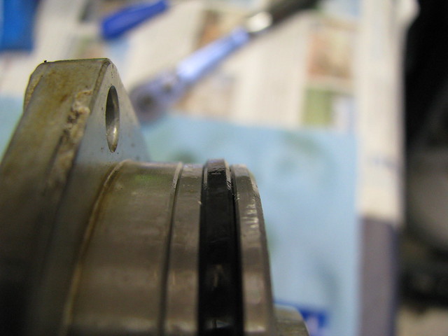 Vanos repair Vanos repair by Sabrebuilder, on Flickr
Well that's some of the engine refurbishment done successfully and one possible source of the rattle.
More updates to follow in the next few days....
....peter
Last edited by peterux; 5th November 2017 at 16:42..
Reason: spelling
|
7th November 2017, 09:41
|
|
Senior Member
Enthusiast
|
|
Join Date: Mar 2005
Posts: 3,080
|
|
Hunt the rattle....part 2
Next I wanted to remove the timing chain cover to inspect the timing chain guides.
First you lock down the secondary chain tensioner. I used a small drill.
 Engine strip and Inspection Engine strip and Inspection by Sabrebuilder, on Flickr
You can then remove the camshaft sprockets and chain.
 Engine strip and Inspection Engine strip and Inspection by Sabrebuilder, on Flickr
 Engine strip and Inspection Engine strip and Inspection by Sabrebuilder, on Flickr
 Engine strip and Inspection Engine strip and Inspection by Sabrebuilder, on Flickr
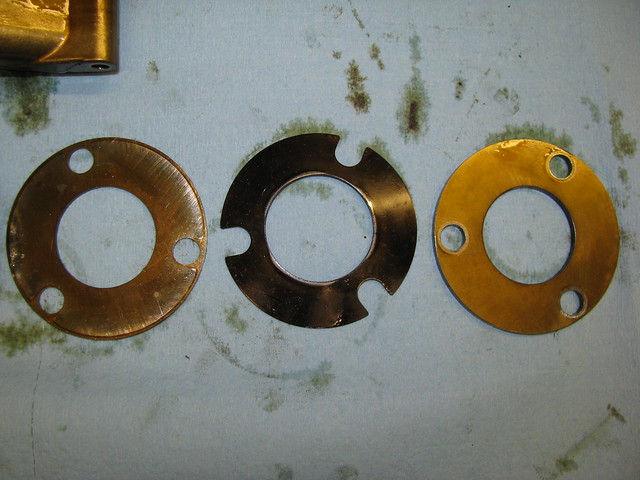
Earlier engines do not have the friction plates but mine had these already fitted.
Then you remove the crankshaft bolt and pulley.
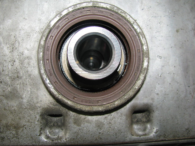 Engine strip and Inspection Engine strip and Inspection by Sabrebuilder, on Flickr
Then you can remove the secondary tensioner. Some wear but already 100k+ miles so probably good for another 100k.
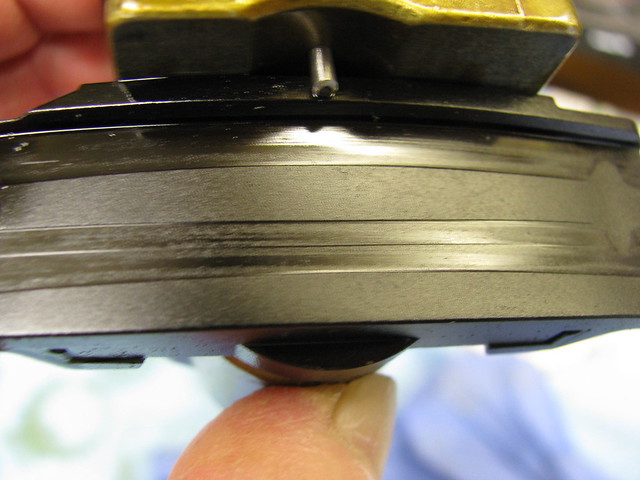 Engine strip and Inspection Engine strip and Inspection by Sabrebuilder, on Flickr
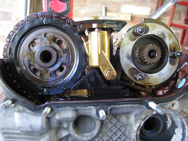
Now with all the bolts removed you can remove the timing chain cover.
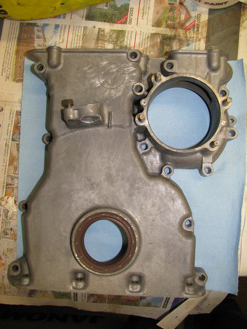 Engine strip and Inspection Engine strip and Inspection by Sabrebuilder, on Flickr
(Photo after cleaning)
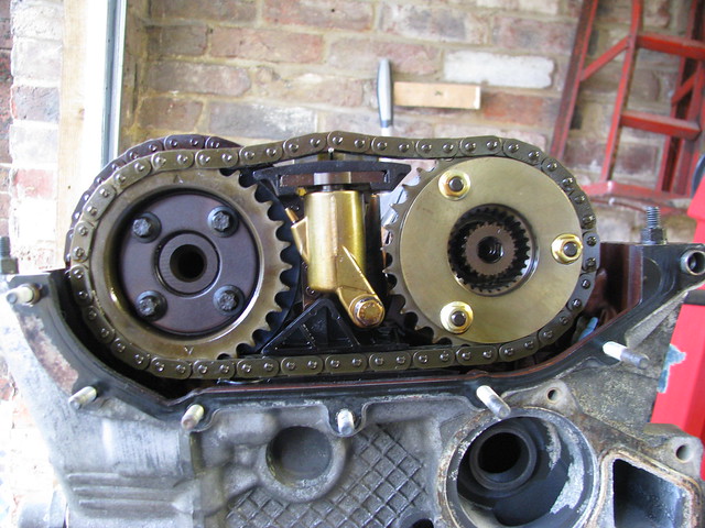
After a good look inside I was surprised to see the amount of slack in the oil pump drive chain....(apologies for the poor video)
Click on image below to take you to Flickr where you can view the videos
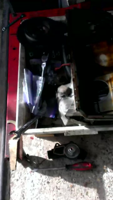 BMW M52 Oil Pump chain BMW M52 Oil Pump chain by Sabrebuilder, on Flickr
There is no chain tensioner on this engine and I cannot find anyway of adjusting the chain tension. Googling suggest this normal but I cannot find a spec on what is normal. A new chain is only £25 so I decide to replace it.
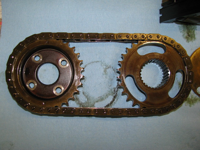
After I fitted the chain deflection was down from 12mm to a much more acceptable 6mm.
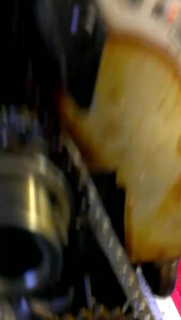 BMW M52 Oil Pump Chain replaced BMW M52 Oil Pump Chain replaced by Sabrebuilder, on Flickr
I think this was the main source of my rattle on start up.
That completes the planned mechanical refurbishment. Now I plan to clean up all the parts, paint them and re-assemble with new seals and gaskets.
...peter
Last edited by peterux; 7th November 2017 at 09:47..
Reason: additional info
|
8th November 2017, 15:29
|
|
Member
|
|
Join Date: Jul 2014
Location: Ealing London
Posts: 54
|
|
work done so far
I have been off internet for a long time and today for the first time I checked your progress and as always, job very well done and I can't wait to see the finished article which I am sure is going to be the best.
|
19th November 2017, 15:01
|
|
Senior Member
Enthusiast
|
|
Join Date: Mar 2005
Posts: 3,080
|
|
Amir - thanks again for your positive feedback. It's taking a while but every little job is one step closer to the finish.
-----------------------------------------------------------------------------
Not a lot of progress in the garage this week due to a bout of 'man-flu' but prior to that I had collected a useful addition to my back yard.
The established method of building a Royale Sabre is to have the central body tub painted prior to the final fitting to the chassis.
For those not familiar with the Sabre here is a picture of the body tub.
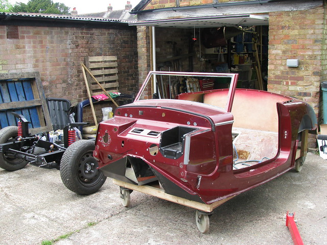 Body tub on trolley Body tub on trolley by Sabrebuilder, on Flickr
It's always been my intention to have the car professionally painted but I plan to do as much of the preparation work as possible bearing in mind the existing paint is in poor condition. I still have some work to do on the tub following the re-shaping of the transmission tunnel but that hasn't stopped me thinking about how I will transportit to and from the painters.
My initial thoughts were to buy a small car trailer and then sell it after I've finished with it so I've had a search running on ebay for some time.
One day this popped up and only about an hours drive from home.
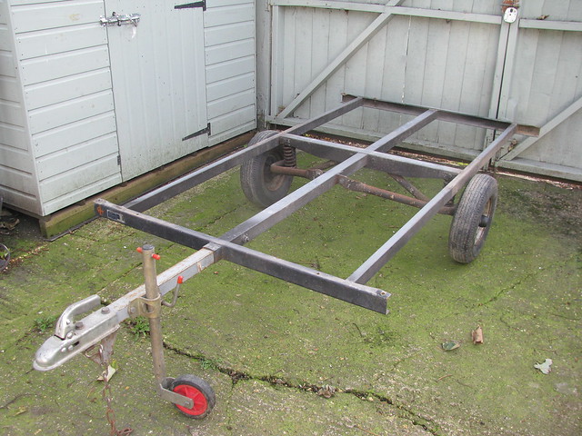 Trailer Trailer by Sabrebuilder, on Flickr
It is the remains of an old Trailer Tent and seems to be just about the perfect size. It's in good condition and has now had a coat of Hammerite to protect it from the elements as it has to live outside. I plan to build a wooden platform to support the tub during transport. But more on that next spring.
Hopefully i'll be back to my engine refurb once my cold subsides.... 
...peter
|
|
Currently Active Users Viewing This Thread: 494 (1 members and 493 guests)
|
|
tajaroman
|
 Posting Rules
|
You may not post new threads
You may not post replies
You may not post attachments
You may not edit your posts
HTML code is Off
|
|
|
All times are GMT +0. The time now is 14:36.
|


 Linear Mode

