|
|
| Marlin Sportster, Cabrio, Berlinetta and Roadster builds Enthused or Confused about your vintage Marlin build? Ask away here or show off your build. |

1st November 2011, 20:24
|
 |
Senior Member
|
|
Join Date: Jan 2011
Location: South Wales
Posts: 378
|
|
 M50 cooling system
evening all,
Does anyone have a schematic showing how the coolant flows through the M50 (or later) engine. I'm trying to figure out in my head where a header tanks should be plumbed in as it was integral to the rad in the donor. I'm not going to be installing a heater and will be short circuiting the flow to the throttle body as it'll not be needed so there is loads of room to simplify the system or even cap off some inlets/outlets.
At the moment the main things that are confusing me are why there are two feeds from the top of the rad to the thermostat housing and in which direction the water flows. Here's a rough diagram of the donor connections but I I'm not sure the flow direction is correct
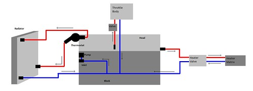
I can only assume that the one side of the thermostat housing allows hot water to the top of the rad for cooling on the O/S and the other side feeds the top of the integral header tank. the bottom of the header tank and cold feed from the rad come together inside where you can't see it hence the single feed out the bottom N/S?
Last edited by morris; 1st November 2011 at 23:29..
|
1st November 2011, 20:59
|
|
Senior Member
Enthusiast
|
|
Join Date: Jan 2007
Posts: 932
|
|
Quote:
Originally Posted by morris

evening all,
Does anyone have a schematic showing how the coolant flows through the M50 (or later) engine. I'm trying to figure out in my head where a header tanks should be plumbed in as it was integral to the rad in the donor. I'm not going to be installing a heater and will be short circuiting the flow to the throttle body as it'll not be needed so there is loads of room to simplify the system or even cap off some inlets/outlets.
At the moment the main things that are confusing me are why there are two feeds from the top of the rad to the thermostat housing and in which direction the water flows. Here's a rough diagram of the donor connections but I I'm not sure the flow direction is correct

I can only assume that the one side of the thermostat housing allows hot water to the top of the rad for cooling on the O/S and the other side feeds the top of the integral header tank. the bottom of the header tank and cold feed from the rad come together inside where you can't see it hence the single feed out the bottom N/S? |
Hi Morris
Very nice diagram, - is this how your donor was?
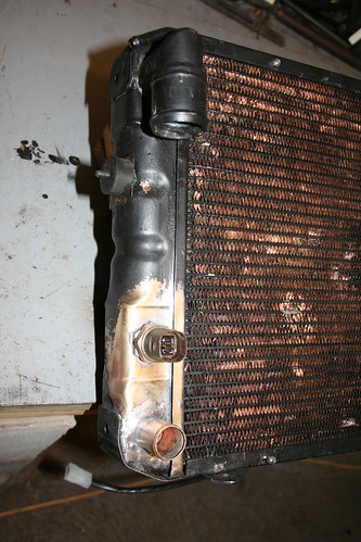
I did not have a donor to work from, as I just bought an engine and gearbox, but I worked on the radiator looking like this:
http://www.gumtree.com/p/cars-vans-m...iator/90732109
I have made my own radiator, and plumbed it in the same as the one above, except as you say for the header tank. I have taken the view that as long as it is plumbed in above the level of the radiator and into the re-circulating head circuit, it does not matter where you join it to the water pipes.

I have altered my radiator since this photo, by adding a new port for the fan sensor, just above the one shown, to allow the standard BMW lower return pipe to connect to the radiator at the lowest point.

|
1st November 2011, 21:16
|
|
Senior Member
Enthusiast
|
|
Join Date: Jan 2007
Posts: 932
|
|
There is a circuit diagram at realoem.
http://www.realoem.com/bmw/showparts...23&hg=11&fg=35 The pipework I received with my engine looked just like this diagram.
Does your pump/thermostat housing look like this?
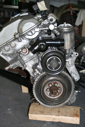
The two main input/output pipes from the thermostat housing go to the top left and bottom right of the radiator. |
2nd November 2011, 00:04
|
|
Senior Member
|
|
Join Date: Jan 2011
Location: South Wales
Posts: 378
|
|
Something weird just happened an my submitted reply disappeared, oh well.
I've updated the diagram as after checking my own photos, the O/S connection on the Rad was at the bottom (drawing done from memory). I'm ok with the stock connectivity as I have all the original hoses and pics but more concerned with the correct way to mod and get rid of the throttle and heater loops. As these are not always on I'm assuming I can just blank them off and build a custom hose from the bottom of the rad N/S to the water pump intake. This all of course depends on my assumptions on the direction of water flow being correct.
I guess what Mike said about the location of the header tank being un-important is true too, I'd assumed the cold feed from it needed to be at the start of the system.
I'd assumed that the hot needed to go in the top of the rad and the cold out the bottom but again, as long as internally the water is routed correctly through the whole matrix and not just straight across the bottom, the physical connection points are irrelevant.
I'm stuck out in Ottawa this week with work and as it turns out I've a fair amount of thumb twiddling time (hence the dodgy drawing from memory) so I'll knock up some more tomorrow to show my options for mods to see what you think
|
2nd November 2011, 20:15
|
|
Senior Member
|
|
Join Date: Jan 2011
Location: South Wales
Posts: 378
|
|
Evening all.
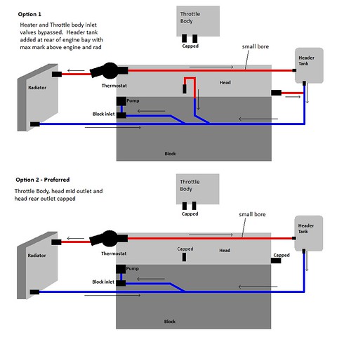
These are the two options I've come up with. Essentially the same though the latter preferred on just caps off the head outlets rather than routing them as per the original system. I've also drawn a bit of perspective on the bottom cold run to show that the bottom of the rad and the block inlet probably should be at the same level.
My plan is to pop the header tank high up in the battery box area as I'd planned on sticking the battery in the back out of the way anyway. That little shelf should accomodate the header tank, clutch fluid bottle and the fuel swirl pot quite nicely leaving precious extra space available in the main engine compartment.
the feed out of the thermostat housing is based on a big assumption that the only reason it has two outlets is to send hot water to both the one side of the stock rad while also going to the header tank. If this is the case then N/S of the thermostat housing in a twin in/out rad can be used, with some heavy step down on on interior diameter, to provide a feed back to the header. Obviously that has to be the harder path to avoid the header becoming the main path for the hot rather than through the rad
Let me know your thoughts as I'm making lots of assumptions having no idea about how the water flows inside the engine or round the pump and thermostat
cheers
Ian
|
2nd November 2011, 20:17
|
|
Senior Member
Enthusiast
|
|
Join Date: Jan 2007
Posts: 932
|
|
Quote:
Originally Posted by morris
Something weird just happened an my submitted reply disappeared, oh well.
I've updated the diagram as after checking my own photos, the O/S connection on the Rad was at the bottom (drawing done from memory). I'm ok with the stock connectivity as I have all the original hoses and pics but more concerned with the correct way to mod and get rid of the throttle and heater loops. As these are not always on I'm assuming I can just blank them off and build a custom hose from the bottom of the rad N/S to the water pump intake. This all of course depends on my assumptions on the direction of water flow being correct.
|
Ian
Why do you want to avoid going through the throttle body? - my experience tells me you should. Many years ago I tuned up a Mini by fitting a special inlet manifold and Weber carb, but thought the inlet heater was not necessary. In winter started to under perform until it would stop completely. Then after half an hour it would start and run fine. I eventually realised the carb was freezing up, and would literally close itself off with ice: years later I had a similar experience with an Audi 100, so would recommend retaining the flow through it.
The car heater can easily be by-passed without issue.
I have used all the standard hoses, except the two between the radiator and pump.
|
2nd November 2011, 20:28
|
|
Senior Member
|
|
Join Date: Jan 2011
Location: South Wales
Posts: 378
|
|
hi Mike, I mainly want to avoid it as it's more plumbing that's not needed. On the stock car it was only there for those extra cold countries where the throttle freezing up is a problem so in the UK probably overkill. I've no intention what so ever of using the marlin at temperatures where it will be needed so figure it's another thing I can do without. All the other cars I've owned haven't had this feature so I figured it's un-important.
on a carb engine having the air warm is important as you say but on a modern fuel injection engine you want it as cold as possible to get the air density up so the ECU responds to the extra O2 by sticking more fuel in and giving you that extra power. I had actually toyed with the idea, as the throttle body has the plumbing, of running a separate coolant through it to bring the temp down rather than warm engine coolant to bring it up as per the original design. I think the space requirements for the refrigerent etc would rule it out in the marlin though plus the extra weight would offset any power gains
|
2nd November 2011, 20:57
|
|
Senior Member
Enthusiast
|
|
Join Date: Jan 2007
Posts: 932
|
|
Quote:
Originally Posted by morris
hi Mike, I mainly want to avoid it as it's more plumbing that's not needed. On the stock car it was only there for those extra cold countries where the throttle freezing up is a problem so in the UK probably overkill. I've no intention what so ever of using the marlin at temperatures where it will be needed so figure it's another thing I can do without. All the other cars I've owned haven't had this feature so I figured it's un-important.
on a carb engine having the air warm is important as you say but on a modern fuel injection engine you want it as cold as possible to get the air density up so the ECU responds to the extra O2 by sticking more fuel in and giving you that extra power. I had actually toyed with the idea, as the throttle body has the plumbing, of running a separate coolant through it to bring the temp down rather than warm engine coolant to bring it up as per the original design. I think the space requirements for the refrigerent etc would rule it out in the marlin though plus the extra weight would offset any power gains
|
That's a fair point about fuel injection I guess, and that you have no intention of using it in winter.
I have to say my engine came with the water pipes attached so I used what there as it was the easiest thing to do, although I eliminated the pre heater control valve. I took the view that it only has an impact in the first few minutes until the engine temperature has built up, and is superfluous after that.
Like you I would be concerned about blanking off the exits around the head, as it may affect the cooling flow, and possibly, capability.
M50s are prone to suffering with head failure if allowed to over heat, so I can see why you were asking about the coolant flow patterns.
|
2nd November 2011, 21:52
|
|
Senior Member
|
|
Join Date: Jan 2011
Location: South Wales
Posts: 378
|
|
The other thing to bear in mind is that the throttle body warming path is only supposed to open up when the mechanical temp sensing valve that went in the original airbox opens due to very low air intake temps. If you haven't connected this into your new bespoke intake duct and just hard wired it through, it will be always on so the engine may not run well as the MAF will setup the fueling based on air intake temp and pressure but then you're artificially warming the air further down the system. won't make a massive difference but worth thinking about.
|
2nd November 2011, 22:15
|
|
Senior Member
Enthusiast
|
|
Join Date: Jan 2007
Posts: 932
|
|
Quote:
Originally Posted by morris
The other thing to bear in mind is that the throttle body warming path is only supposed to open up when the mechanical temp sensing valve that went in the original airbox opens due to very low air intake temps. If you haven't connected this into your new bespoke intake duct and just hard wired it through, it will be always on so the engine may not run well as the MAF will setup the fueling based on air intake temp and pressure but then you're artificially warming the air further down the system. won't make a massive difference but worth thinking about.
|
You are right. I have to say I copied what Marlin and the two other M50 engined owners have done and blanked this off. I have no idea how small, or large, an impact this will have? |
|
Currently Active Users Viewing This Thread: 1 (0 members and 1 guests)
|
|
|
 Posting Rules
|
You may not post new threads
You may not post replies
You may not post attachments
You may not edit your posts
HTML code is Off
|
|
|
All times are GMT +0. The time now is 06:35.
|


 Linear Mode

