|
|
| Sammio Builds and discussions Sammio bodied car builds and specials |

10th February 2015, 21:06
|
|
Senior Member
|
|
Join Date: Dec 2013
Location: Sunny Cumbria
Posts: 470
|
|
I agree with Micky that what he describes is good practice, but I looked it up this morning and according to this site, the rear fog can be independent of any other circuit.
http://www.motuk.co.uk/manual_130.htm
However, for the IVA, it's now required that a special relay is used which causes the rear fogs to go out when main beam is selected, and when the lights are turned off, so when lights are turned on again, or dip beam re-selected you have to turn the rear fog switch back on. I understand all new cars have this feature now. A right pain in the backside in patchy fog. |
11th February 2015, 07:40
|
 |
Senior Member
|
|
Join Date: Feb 2012
Location: Wembley, London
Posts: 5,056
|
|
Micky & Ed - Thanks for the replies. 
The link Ed posted is actually where I found the rules for the switch that I quoted previously.
My understanding is as follows:
- Front fog lights are actually optional
- Rear fog lights are required if your car is "young" enough
- The rear fog light switch can be independent of the rest of the lighting
- However there are also "on the road" rules about using fog lights, that are not part of the MOT
Cheers, Paul. 
|
12th February 2015, 12:59
|
|
Senior Member
|
|
Join Date: Feb 2012
Location: Wembley, London
Posts: 5,056
|
|

I seem to be struggling to shake off the "lurgies", so I'm still taking it very easy.
More Dash Board Wiring:
I started with a basic test of the fog light switch & fog lights by-passing the loom.
( Earth wires to one side of the battery & "live" wire to the other. )
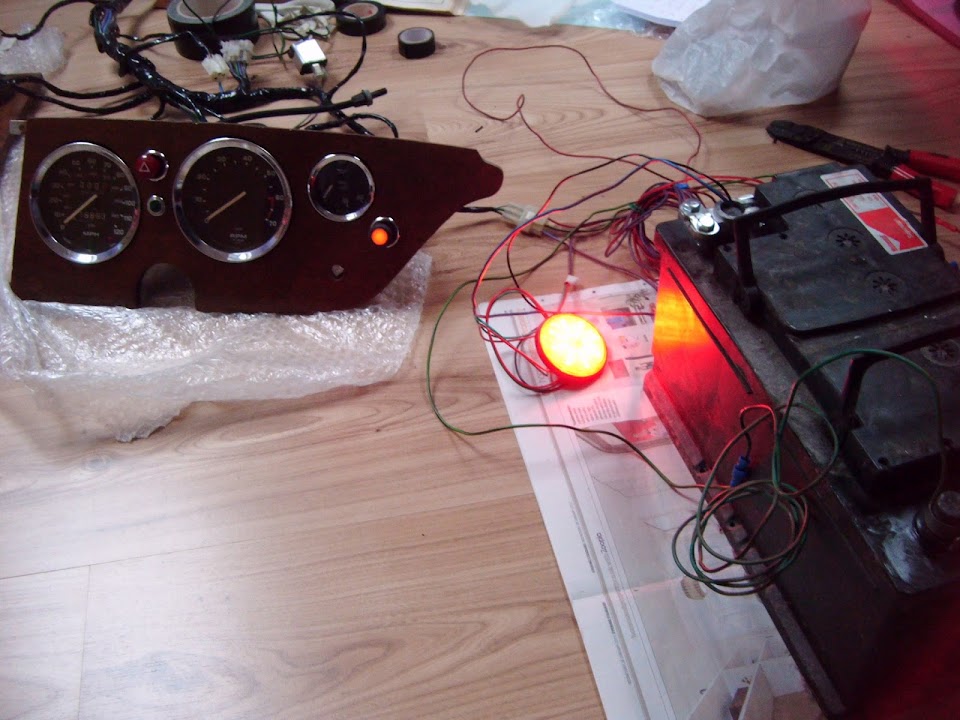
It was a great relief to see both the switch light & the fog light come on.
In my bag of spare wiring I found a wire with the right connection fitted for the block already in the loom.

So my next test was with the "live" wire connected to the loom & the loom connected to the battery.
But it didn't work. 
Then I figured that maybe the steering column switches needed to be connected, even if they are not switched on.
So I removed the steering column from the car and brought it inside to play with.
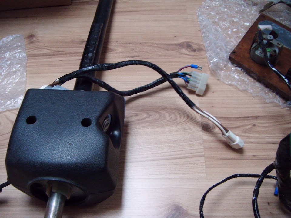
Unfortunately, even with these blocks connected, it still wouldn't work.
It was only at this point that I noticed the connecting block for the hazard lights was hanging free. 
Once that was connected, the fog light switch was operational again.


So, safe in the knowledge that the wiring was in order, it was time to tidy it all up.
I started wrapping the wire from the switch to the fog lights to the outside of the loom.

Then I reached the area where the side repeater extensions had been removed.
( This is also where the new connection is being made. )
Next I simply joined the wire with the correct fixing on one end to the "live" wire from the fog light switch

Then I could plug the wire into the connecting block & wrap it all up.

Again, the live wire would remain on the outside of the existing loom, along with the wire for the lights.

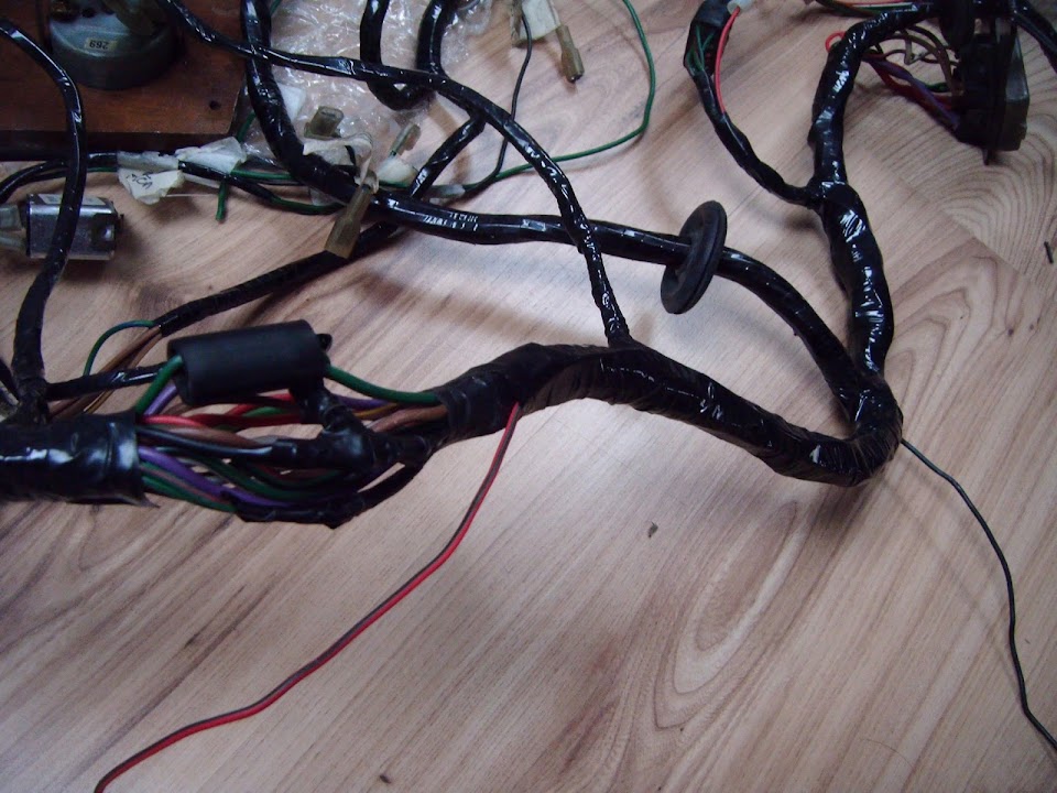
Eventually these two wires reached a point in the loom where I could create a new "spur".

I just needed to bring the fog light earth wire down from the connecting block to this point & then wrap all three wires together.

Note:
Not easy to see in the photo, but the earth wire from the connecting block comes out of the loom on the other side of this new spur.
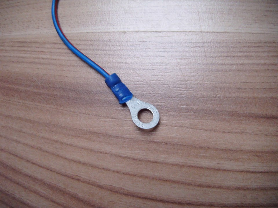
Which just left me with the other end of the earth wire to finish off, so I fitted an "O" ring connector.
Overall I am happy to have made another little bit of progress, despite not feeling great.
Take care, Paul.

|
13th February 2015, 14:01
|
|
Senior Member
|
|
Join Date: Feb 2012
Location: Wembley, London
Posts: 5,056
|
|
Clutching At Straws:
Even for me, it would be a long stretch of the imagination to call the following a progress report.
But too many other things are getting in the way at the moment.
Still, while it is raining outside, I can at least do a bit more testing of the wiring loom inside.
Over the weekend, I will re-locate "downstairs", as this is taking up too much space in the bedroom. 

The news is that both the car horns work when I press the stalk on the steering column.

The bad news is that I did not anticipate impact our loft conversion's sloping roof would have on the sound.
Top Tip:
Do NOT test your car horns indoors, a few inches from your head, as you will end up with some serious ringing in your ears.

At this point I remembered it was Friday the 13th.
So my planned lighting tests were put on hold incase I managed to connect myself to the mains electricity by mistake.

- - - - - - - - - - - - - - - - - - - - - - - - - - - - - - - -
Shopping Update:
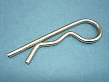
I've ordered a few stainless steel "R" clips:
- Two for the bolts used with the bonnet hinges.
- Four for the bolts mounting the internal frame work to the chassis.
The small set of cobalt drill bits I previously ordered has already arrived.

I really hope these will allow me to drill the holes required in the bolts for the "R" clips. 
- - - - - - - - - - - - - - - - - - - - - - - - - - - - - - - -
Until next time, take care, Paul.
|
13th February 2015, 16:46
|
|
Senior Member
|
|
Join Date: May 2013
Posts: 2,161
|
|
Good stuff Paul! I hope my loom all works when I get round to doing it, at least it did all work on the car before I started the build.
Having had such a crappy day yesterday, I took the advice I was given and took Friday 13th off!!
|
13th February 2015, 22:38
|
 |
Senior Member
|
|
Join Date: Sep 2011
Posts: 1,446
|
|
You may want to grind a small flat to assist the drill to start off they don't really like going into round bar and will wander ...I do quite a bit of drilling stainless bolts on an item I sell...so actually had a jig built that holds the bolt with a guide for the drill bit to stop it wandering.....a pillar drill and vice makes things easier if you have them
Are you making lanyards for the r clips.?
Here's mine
[IMG] 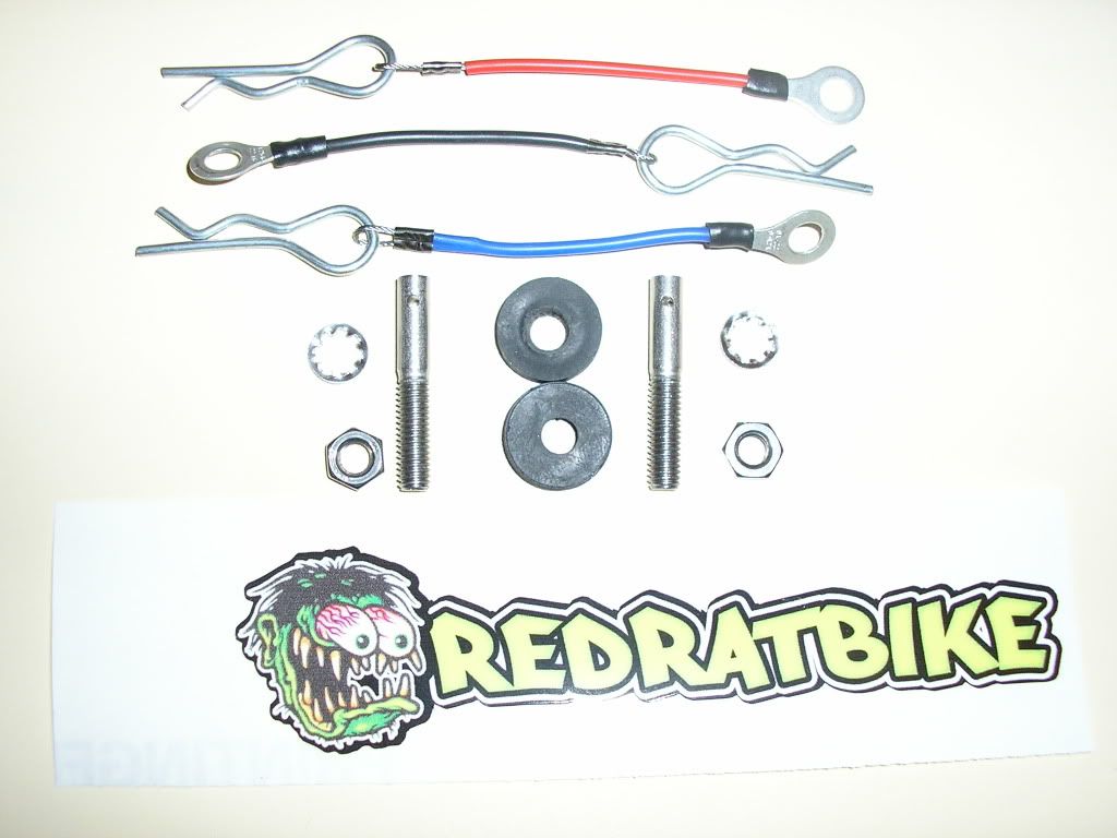 [/IMG]
Last edited by redratbike; 13th February 2015 at 22:45..
|
14th February 2015, 06:58
|
 |
Senior Member
|
|
Join Date: Jul 2011
Posts: 5,328
|
|
On bolts and threaded bar you can also drill a guide hole through a nut, lock it in place with a second nut and drill through that. You need a steady hand (or preferably a pillar drill) to get the hole straight through the centre of the piece, but it stops the bit from wandering when starting the hole.
|
14th February 2015, 16:11
|
|
Senior Member
|
|
Join Date: Feb 2012
Location: Wembley, London
Posts: 5,056
|
|
Scottie - All the electrics worked on my donor too, but I have made quite a few mods since then.
So I am still really pleased when I manage to get even a simple light to come on correctly.
RedRatBike & Mr T - Unfortunately no pillar drill, vice, or workbench.
So thanks for the other drilling tips, as I was wondering about how to drill through the thread.
I wasn't planning on fitting lanyards, as I'm just using these R clips as an alternative to a split pin.
- - - - - - - - - - - - - - - - - - - - - - - - - - - - - - - -
It must be love...
I had no intention of spending any of Valentine's Day working on the car.
But my wife wanted to get on with a few of her own things, so she gave me her blessing.
More Wiring Work - Part 1:
In order to sort out the wiring loom for the front headlights and indicators, I needed to head outside.
A bit of a risk, given this is what the sky looked like when I started.

I had already disconnected the dashboard wiring, so I could bring the loom out to the car.

I've had a look at my old photos and can't seem to find any showing the route the loom originally took.
However, there are two cable clamps along the passenger side of the chassis that look the part.

Similarly, the new car horns that came with my donor had not been fitted, but they could be mounted here.

There is certainly enough wiring to connect the two horns together if mounted here.
( I've just rested the horns on the chassis for the photo. )
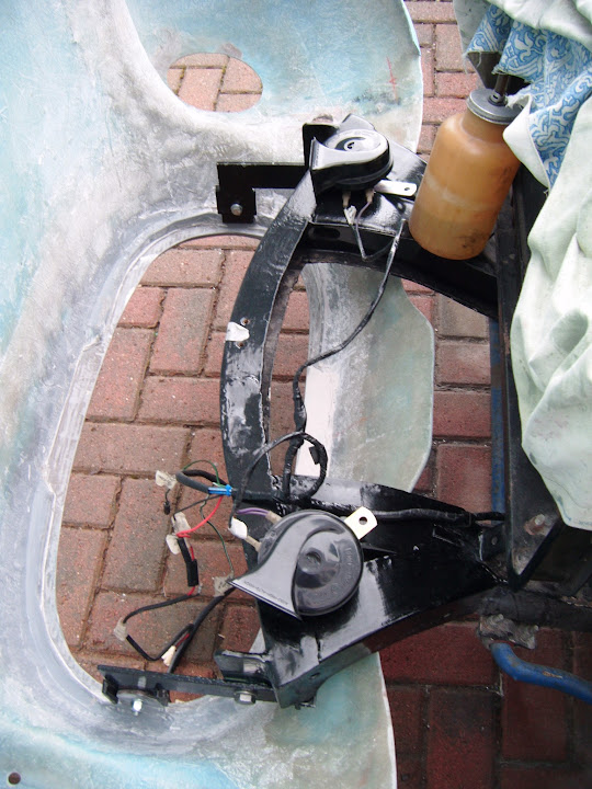
Next I taped one of the headlight shells into position, aligning it with the adjustment holes.

With an indicator also taped into position, I could get a rough idea of the cable routing.
By the time I have clipped these in place, there will be the flexibility for the bonnet to open & close, without fouling the hinges.
Some of the wires for the driver's side headlight will reach across with no problems.
( See the wires in front of the chassis. )

I say some of the wires, because I need to extend two more "live" wires across to the driver's side:
- One for the side light, which is now built into the new headlight.
- The other for the indicator.
I also need to build a new "spur" to divide the loom across each side to work with the new connecting plugs I've fitted to the lights.
Finally, I need to add some extra earth wires into the mix too.
So everything was brought back indoors and this was the area I needed to work on.

So that was unwrapped.

Next I changed the connections on the driver's headlight wires.

Note:
I did trim off the stray wire after taking the photo.
Then I used some spare red wire as the live feed for the side light and joined all four wires to the block.
Next I opened out the ends of some O rings so they could be earthed to the horn mounting bolts.

Then I used some more spare wire to connect to the indicator block & the new earth lead.

Then I could join the driver's indicator and headlight connectors together.

Obviously I need the loom wire for the indicator to be longer, as the wires from the back of the light are shorter.
I was then able to pull the wire for the passenger indicator away from the area I had unwrapped earlier.
Then I joined that and another earth wire to a connecting block.

End of Part 1...
Last edited by Paul L; 14th February 2015 at 16:11..
Reason: Copy & Paste Error!!
|
14th February 2015, 16:12
|
|
Senior Member
|
|
Join Date: Feb 2012
Location: Wembley, London
Posts: 5,056
|
|
More Wiring Work - Part 2:
So now I had the two spare wires running along from the driver's side like so.

I knew there was "slack" in the wiring, so a couple of snips later.
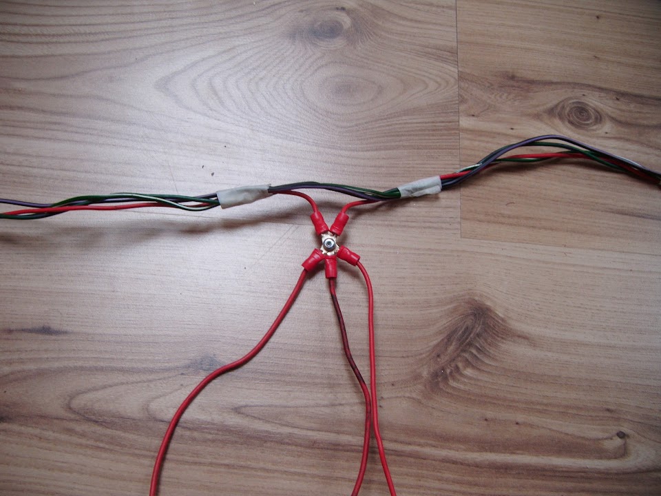
In order to build the spur for the passenger headlight, I make a three way connection like this.
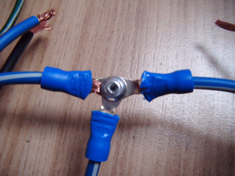
I had to make 4 of these 3 way connections, plus one simple singe wire connection for the driver's indicator.

Then I fitted another connecting block on the end of the spur and wrapped everything up.
Not a great photo, but this gives you a rough idea of the loom layout now.

Right I need to tidy up this mess before doing some cooking later on for my very understanding wife.
So until next time, take care, Paul.
PS
Spitfire Owners - I need your help:
I mentioned earlier that I couldn't find any photos of the original Spitfire loom route.
So does anyone have any photos of where the wiring from the alternator goes?
I need both the route to the bulkhead and the route to the headlights.
Thanks.
|
15th February 2015, 16:59
|
|
Senior Member
|
|
Join Date: Feb 2012
Location: Wembley, London
Posts: 5,056
|
|
I know that lots of photos of wire are not very interesting, especially when they aren't always pin sharp either.
But I do find it very helpful to remind myself what I was doing and why, so here is today's progress report...
- - - - - - - - - - - - - - - - - - - - - - - - - - - - - - - -
Yet More Wiring Work - Part 1:
The good news is that Google images has given me a pretty good idea of where to route the alternator wires.
( And where the wires to the headlights & horns need to go too. )
The bad news is that this photo of a Spitfire bonnet / battering ram also turned up in my search. 

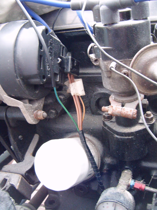
Once my eyes had recovered I put some thought into the wiring for the rear lights & fuel gauge.
I went back to this photo that I had previously taken when looking at a possible wiring route.
Initially I had intended to shorten the loom, so the was just enough wiring to reach the lights.
However, it occurred to me that there is nothing wrong with keeping the wires their original length, even if they are too long.
Whereas the same can not be said for having wires that are cut too short!
So to save myself a bit of time & effort, I have decided to leave the loom as it is & "just" add the connectors.
I also worked out that the earth wires are all local to the back of the car, not joined to the wiring loom at the front.
This was a big step forward in really understanding how the loom works and why things were wired the way they were.
It also makes re-routing the fuel gauge sender much easier, as I just need to find a new earthing point.
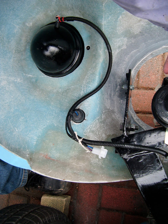
Again this is an old photo and I need the wires to go to the front of the petrol tank, not the rear as per the Spitfire set up.
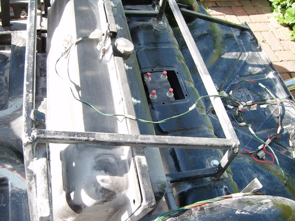
That last photo is this area of the loom.

The wiring route was linked to the earthing point, so after a quick snip, the earth wire is now independent of the rear loom.
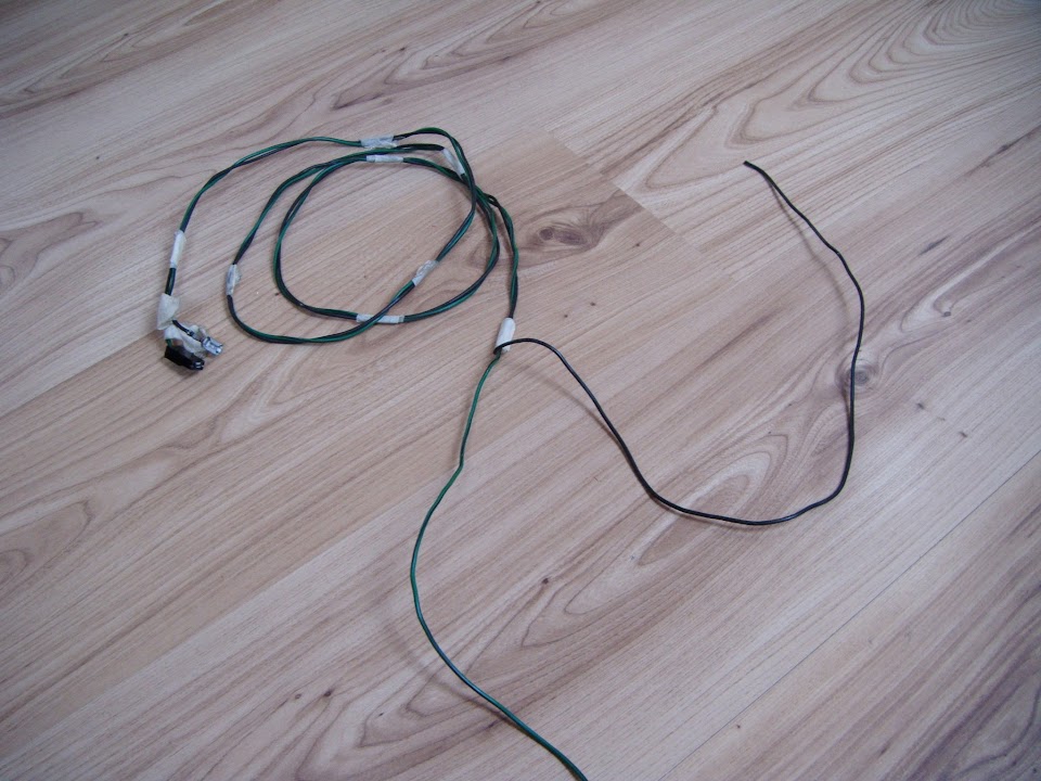
Next I taped the wire for the fog light to the rest of the rear loom wiring.
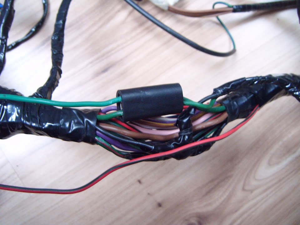
I ran it all the way to this first "junction" in the loom.
Running left to right, the "power" wires are:
- Fog lights
- Passenger indicator
- Stop light
- Tail Light
Plus the original earth wire that I am going to replace.
Note:
You can see that the stop and tail light connections also have a wire continuing to the driver's side.
( With a separate green & white wire for the indicator on the driver's side too. )
I now needed to add another spare wire for the driver's side fog light to the passenger side connection.

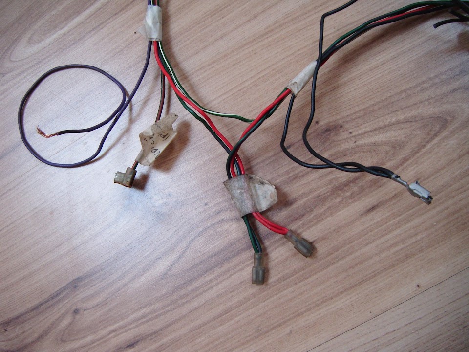
Then I needed to sort out the loom connections for the three lights on this side.

Note:
I had to buy a replacement indicator for one I had already wired up before it then got damaged.
So I just needed to add a connecting block to this new indicator.
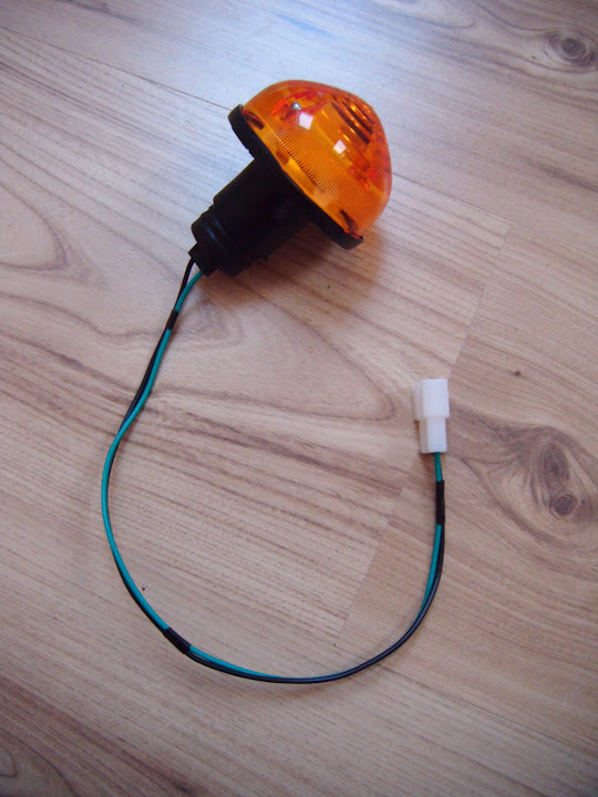
I also put a connector on the earth wire from the fog light.

I found this "spare" three way earthing point.

Although if I'd thought about it a bit more, I would not have kept the wires the same length.
( See below. )
I did add the corresponding connectors to each earth wire.
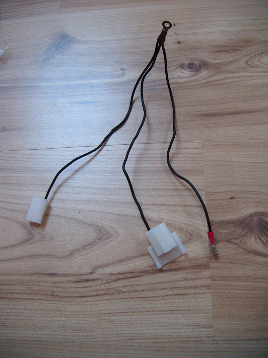
So by the time I'd joined the original loom wires to these connectors it looked like this.

Note:
If I had left one earth wire a bit longer than the others I could have made a neater, single, spur.
But as it is, all three lights on the passenger side can be easily connected to the loom.

End of Part 1...
|
15th February 2015, 17:00
|
|
Senior Member
|
|
Join Date: Feb 2012
Location: Wembley, London
Posts: 5,056
|
|
Yet More Wiring Work - Part 2:
You can also see how the two "power" wires for the driver's side are fixed to the loom connector.
Then I simply wrapped this section up.

Before pulling out all the original earth wires and leaving them in the "middle" where the number plate lighting will go.
This was the end of the rear loom on the driver's side, which now included the spare fog light wire.

Learning my lesson from the passenger side, this time I started by adding the connectors to the loom first.

Then I added 3 new "uncut" earth wires to the connectors.

Then I cut the earth wires to size and fitted an "O" ring connector, which left a "clean" single spur for the earthing point.

I will come back and finish the number plate light wiring another day.
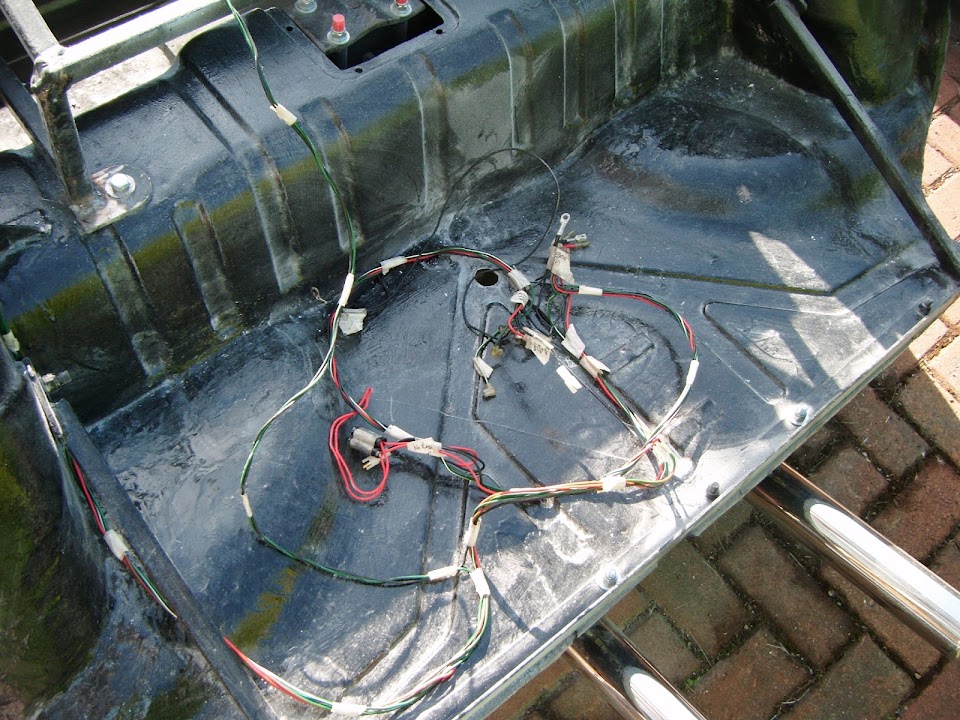
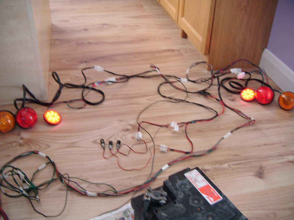
But for now, this is how the rear loom and rear lighting will look.
( Sorry this is a very blurred photo. )
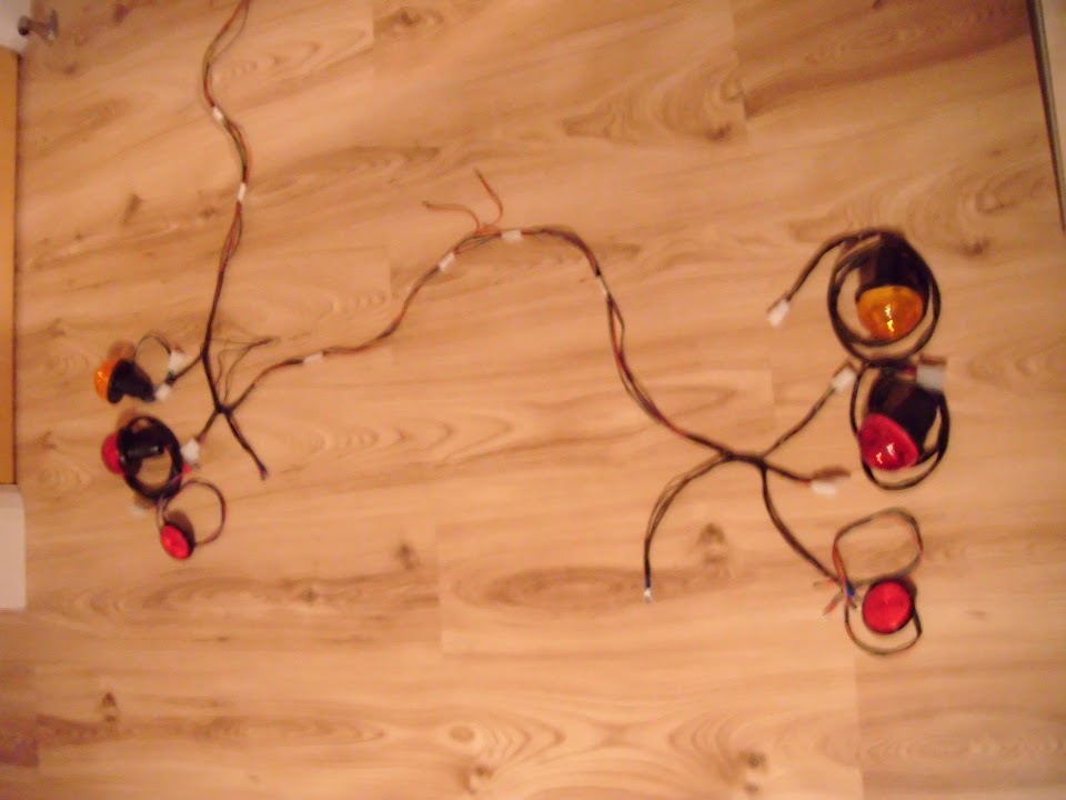
At least this means I should be able to test all the lighting before re-fitting this to the car.
Until next time, take care, Paul.
|
15th February 2015, 18:52
|
|
Senior Member
|
|
Join Date: Dec 2013
Location: Sunny Cumbria
Posts: 470
|
|
Paul, a suggestion...
On cars with chassis and 'bits' (like wings, bulkheads and bonnet) it's very good practice to have an earth continuity wire capable of taking over if a 'local' earth fails. Nine electrical faults out of ten can be traced to bad earths. On fully welded bodyshells it isn't such a problem but when so many components are bolted together and there has been a lot of paint to prevent corrosion and grunge used to fill gaps, electrical continuity of the earth isn't always as reliable long term as you may hope.
Speaking as somebody brought up on Alvis's, Land Rovers and a variety of cars with chassis and metal or wooden frames, I have always used a continuity earth whenever possible. It's not hard to do at this stage but at some point in the future you will appreciate the benefits.
I usually use a good capacity 7 core caravan cable with a heavy earth wire to feed the back lights etc. I don't rely on the chassis at all in my circuit wiring. Perhaps sounds like belt and braces but on a cold wet night when for some inexplicable reason your back lights fail on the motorway... Chances are it will be a bad earth.
Last edited by 8 Valve Ed; 16th February 2015 at 07:26..
Reason: typo
|
16th February 2015, 11:01
|
|
Senior Member
|
|
Join Date: Feb 2012
Location: Wembley, London
Posts: 5,056
|
|
Ed - Thanks for the "earth continuity wire" tip.
But can I just check I have understood what I need to do?
In the case of the rear lighting I will have 3 earth points for the lights (left, right & middle).
Does this extra earth wire join each of these three points to another earthing point?
- - - - - - - - - - - - - - - - - - - - - - - - - - - - - - - -
Number Plate Lights:
This is one area where I have found myself consistently dithering over the final design.
I originally bought 4 LED number plate light bolts & planned to use them to hold the plate in position & light it up.
That way, there would only be the number plate at the back, with no "traditional" light above it.
Then I bought some "normal" number plate lights to see if they would be a better bet fitted to the sides.

Then I saw this photo of a Spyder that used two LEDs fitted either side of rear number plate.

I had planned to copy this approach, but as I've reached the point of sorting out the wiring loom, more doubts have crept in.
So rather than waste any more time on this, I have decided on a final design and I am going to stick to it.
Rather than use 2 LEDs on either side of the plate, I am going to use 3 LEDS mounted above the top edge of the number plate.

This should be more than enough to light the plate, especially as the red car above passed an MOT with just 2 fitted.
The number plate will then be fixed to the body shell with some normal yellow plastic bolts.
In addition, this approach will maintain the space between the number plate and the lights seen in this photo for the DVLA.

Notes:
This the oversized plate that came with my donor and I already have a smaller one to fix.
As my donor car is a "V" reg, but with only 2 numbers, giving me six characters in total.
Anyway, with a decision finally made, it was time to sort out the wiring...
The LED connector needs to fit through a small hole & these blades appeared to work.

This was the original Spitfire junction for the number plate lights.
( As the red wire also powers the rear tail lights. )

As I needed to wire each LED up individually, I added three wires to this junction.
And wrapped it all up.

This gave me more than enough slack to reach the LEDs when mounted above the number plate.

In addition to fitting blades to the 3 LEDs, I had also fitted the other ends on the loom wires.

At this point things started to go a bit pear shaped as I looked at the option of a "blue" blade fitting for the new earth leads.
I thought I'd better double check that these would also fit through the LED mounting hole.
So I undid the nut, tried to remove it and it jammed against the blade. 

Yes, whilst the blade fitted through the washer, I hadn't thought to check the nut, which has a smaller internal diameter.
After a bout of swearing I remembered the connecting block I'd previously used to test the LEDs.
So I simply cut off the connections I'd already fitted and will use small sections of this block instead.

Whilst this is not a quick release arrangement, at least I will still be able to disconnect the LEDs from the loom if required.
With the power wires finally sorted out, I used three wires to set up an earth spur and joined them to the connecting blocks.

I've got a few other chores to get on with now, but hopefully I will get a chance to start testing the lighting soon.
Cheers, Paul.
|
16th February 2015, 11:43
|
|
Senior Member
|
|
Join Date: Dec 2013
Location: Sunny Cumbria
Posts: 470
|
|
Quote:
Originally Posted by Paul L

Ed - Thanks for the "earth continuity wire" tip.
But can I just check I have understood what I need to do?
In the case of the rear lighting I will have 3 earth points for the lights (left, right & middle).
Does this extra earth wire join each of these three points to another earthing point?
|
Yes, you can do it that way, whatever is most convenient and economical of wire. if the earth points are not the actual chassis and even if they are and are subject to weather, moisture ingress or a mixture of metals, like aluminium panel, steel bracket, stainless bolt and brass eyelet terminal.
In many cases it's dissimilar metals which cause the corrosion in the connection, corrosion causes resistance. This may show up as a good connection with a test meter but won't pass current, which can make diagnosis difficult. This is why I try to run a cable directly from a known good, clean dry and 100% earthing point, if there are as few earthing points as possible that's fewer places to look if there is an earthing fault.
With the Berlinetta I will have two, one at the back, on or near the battery earth switch and the other on the front bulkhead which in turn will be bonded to the chassis and the engine from a really good welded on tag on the chassis. The front lights will be bonded to one of the good front earths, probably the chassis side of the engine bonding strap.
|
16th February 2015, 21:33
|
|
Senior Member
|
|
Join Date: Apr 2014
Location: Midlands
Posts: 405
|
|
Hi Paul, I have used quick release connectors for all of my light fittings, mainly for the front so it could be removed easily if needed.
I got them off amazon - http://www.amazon.co.uk/gp/product/B...ilpage_o02_s00
I used the three pin variety for headlight and tail lights too.
Although no instructions came with them they are simple to put together - I would highly recommend.
PS I enjoy reading your progress, I wish I could work on my car during the week too it seems thats when the dry weather appears at the moment.
All the best, Ian |
18th February 2015, 07:13
|
|
Senior Member
|
|
Join Date: Feb 2012
Location: Wembley, London
Posts: 5,056
|
|
Ed - Cheers.
Ian - Matching available car building time with dry weather is always an issue when building outside.
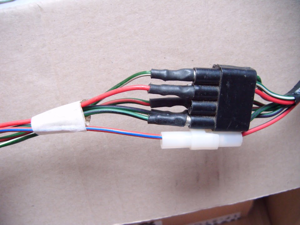
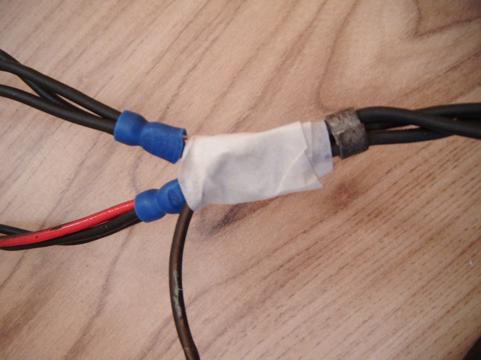
I have fitted quick release connections to all the lighting (front & rear) with the exception of the fog lights & LED number plate lights.
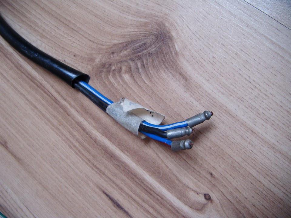
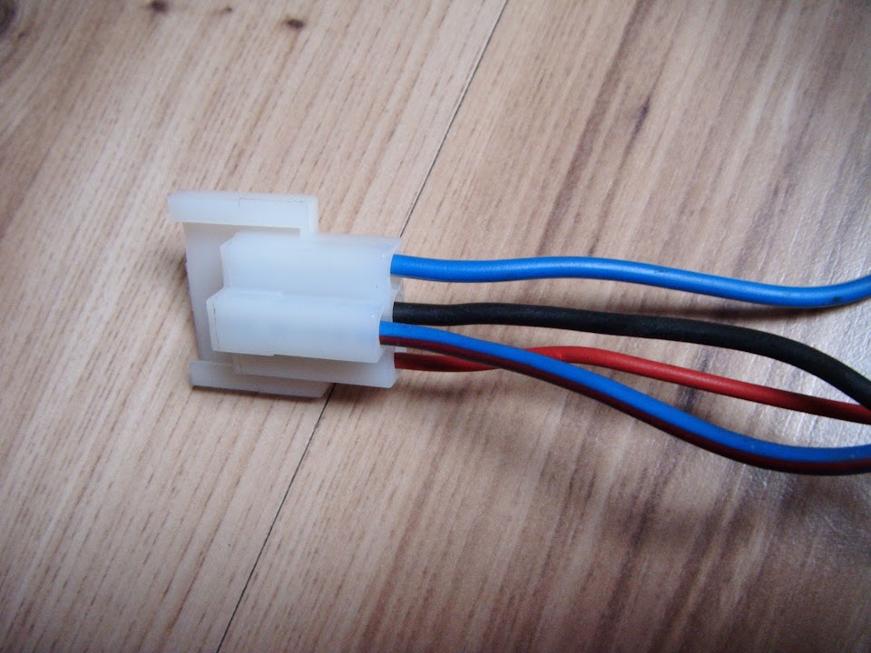
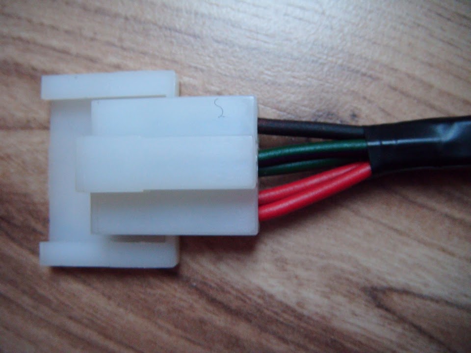
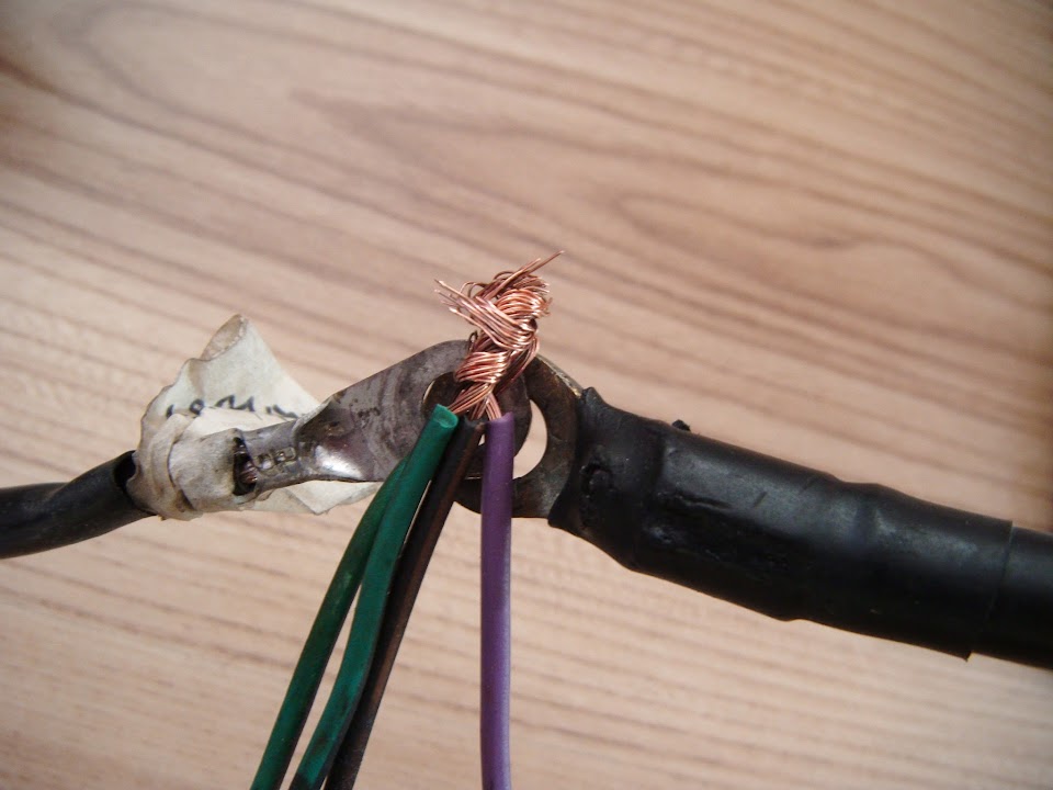
Although I know what you mean about the lack of instructions, as I managed to wire up one connector back to front.
Initially I did this:

When I should have done this:
( Excuse the poor photo. )
- - - - - - - - - - - - - - - - - - - - - - - - - - - - - - - -
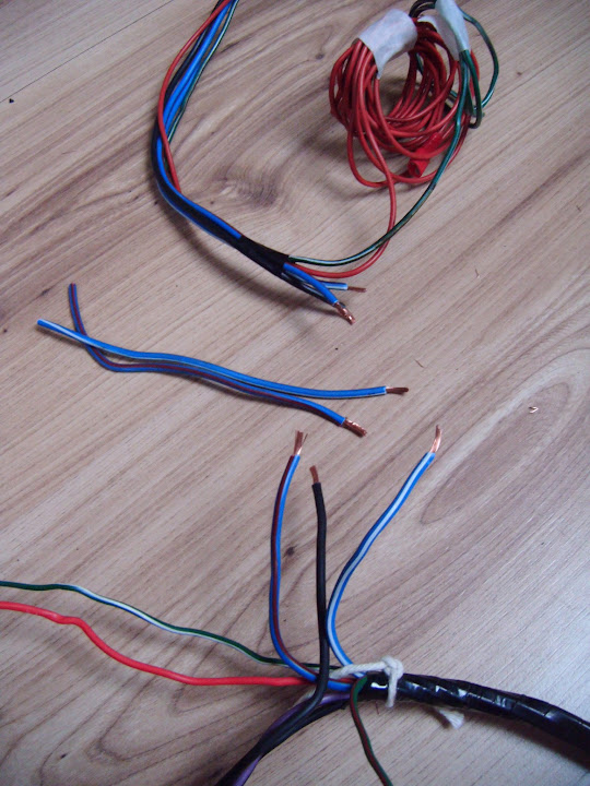
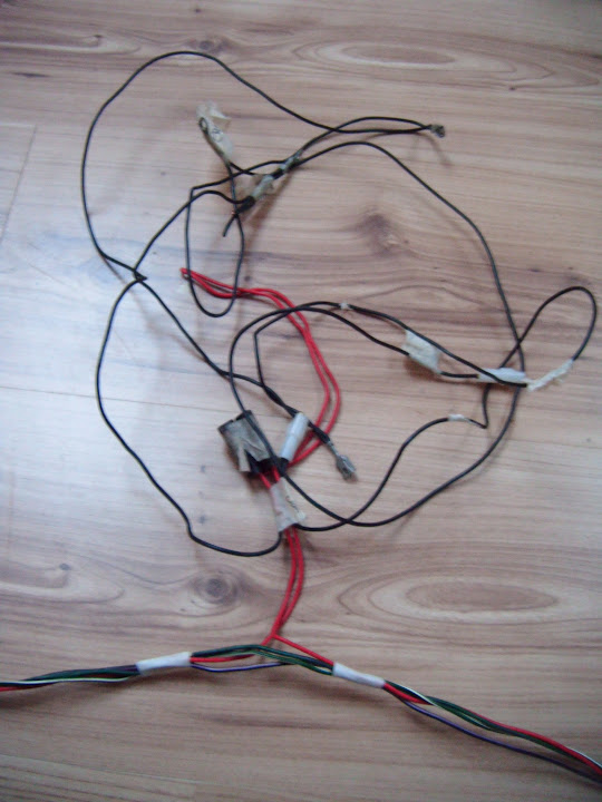
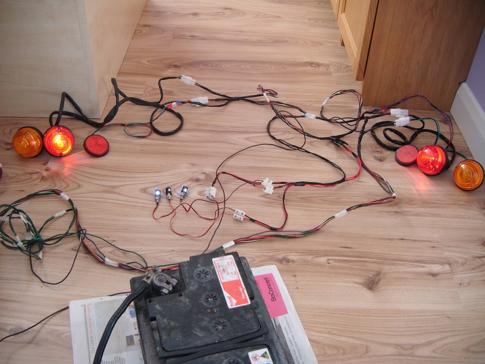
Nothing to see here:
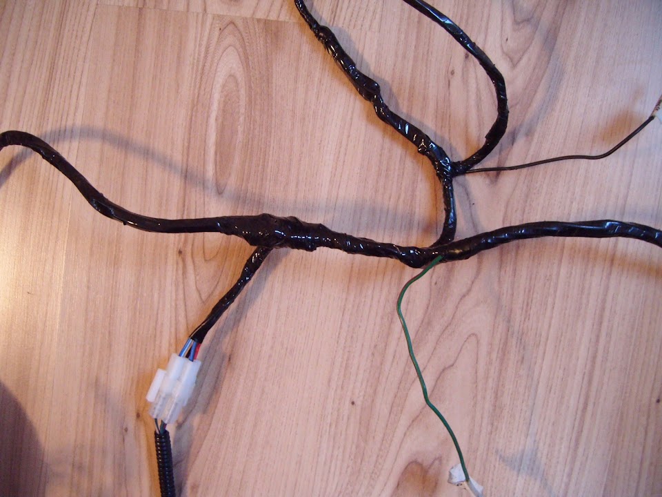
Only thing I can add at the moment is a better photo of the final rear loom layout from the other day.

I will finish wrapping the wires up after I finally get the chance to test the lights.
Cheers, Paul.
|
18th February 2015, 07:43
|
|
Senior Member
|
|
Join Date: Jun 2011
Location: birchington, kent
Posts: 1,769
|
|
Looks very neat, looks like a nice day and its getting lighter.
|
18th February 2015, 13:45
|
|
Senior Member
|
|
Join Date: Feb 2012
Location: Wembley, London
Posts: 5,056
|
|
Gary - Thanks, the wiring is one of the few areas where I want it to be functional and look the part too.
I've noticed the evenings getting lighter and the two cherry blossoms in our garden are just starting to bud.
When they are in full flower I know that Spring is on its way and the worst of the Winter is over.
Unfortunately, despite it being a lovely day outside, I was confined to quarters on half term child care duty.
Still, it wasn't all bad news, as I did manage to make some good progress with my wiring (see below).
- - - - - - - - - - - - - - - - - - - - - - - - - - - - - - - -
Testing - Part 1:
One of the advantages of having children at secondary school age is that they are in no rush to get up in the morning.
So while the children were asleep, I set up the loom for some testing.
As before, please excuse the poor quality of some of these indoor photos.
I had to start by making some temporary connections so that all the earth points could be connected directly to the battery using some spare wire.
Note:
I did at least wrap some tape around this last connection before I started.
First up were fog lights, as these had already been tested and they should confirm the earthing points were working.
Next it was the first "step" of the headlight switch, which should bring on the running lights.
Head Light - Side Lights x 2 - Check

Tail Lights x 2 - Check
LED Number Plate Lights x 3 - Check

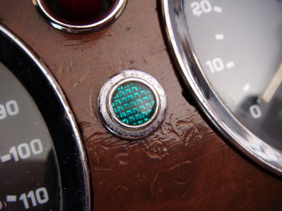
Dash Board Dial Lights x 5 - Check

Note:
It was easier to see if these lights were working when there were pulled out of the gauges.
Then it was the second step of the headlight switch, which should bring on low beam.
Head Lights (dip) - Check

Then I used the steering column headlight switch for high beam.
Head Lights (main) - Check

The main beam indicator on the dash also lit up, although it was very faint.

Then I needed another bodge to test the rear brake light switch.
( As the wiring from the loom will drop down below the dash to the brake pedal, where the switch is. )
Brake Lights - Check

So far, so good, but very little on this build has been trouble free and the wiring is no exception.
Where it all started to go wrong was with the indicator / hazard light circuits.
End of Part 1...
|
18th February 2015, 13:47
|
|
Senior Member
|
|
Join Date: Feb 2012
Location: Wembley, London
Posts: 5,056
|
|
Testing - Part 2:
Note:
Taking some of the following photos of lights that were flashing was not as easy as it might sound.
First I used the steering column indicator switch, starting with the up position for "left".
Front Passenger Side Indicator - Check

Rear Passenger Side Indicator - Check

Dash Board Indicator Light - Fail
Then I tried the down position for "right".
Front Driver Side Indicator - Fail

Rear Driver Side Indicator - Fail

Dash Board Indicator Light - Came on, but didn't flash, so really another fail.

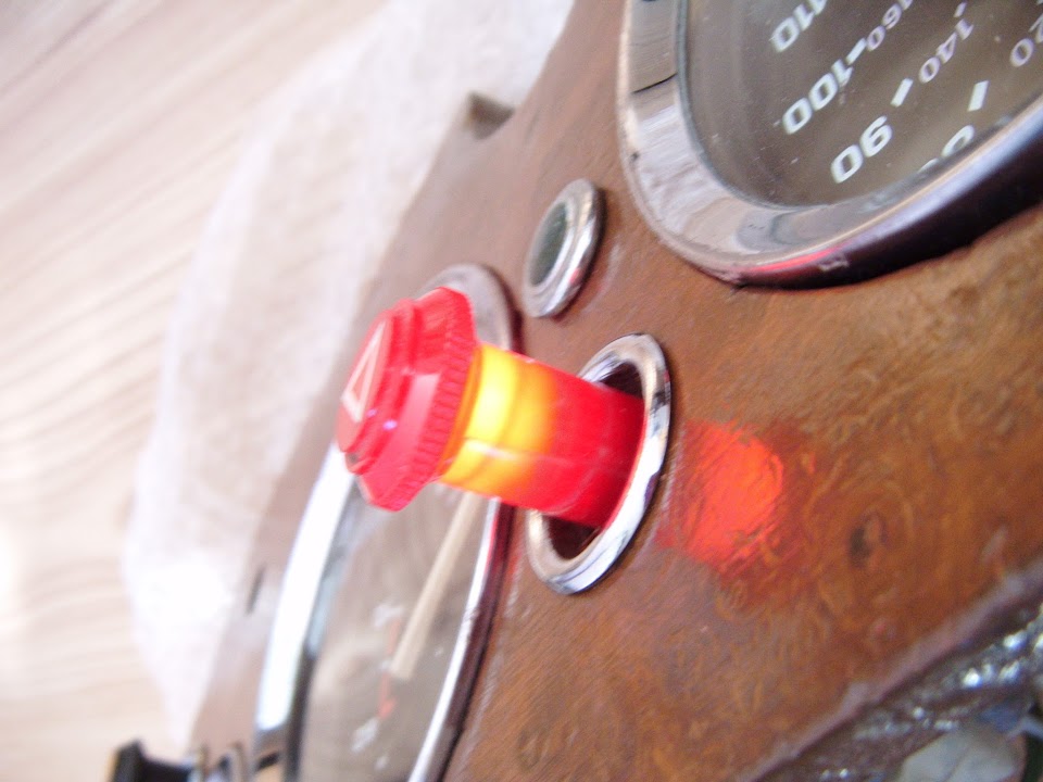
Then I left the indicator switch off, and tried the hazards instead.
This time the light in the switch came on & flashed.
But only the indicators on the passenger side worked, still nothing from the driver's side.
Trouble Shooting:
I started by swapping both the front & rear indicators around, as the connections from the lights are the same.
Now the "passenger" side indicators came on when there were connected to the driver's side of the loom.
But the driver's side indicators didn't come on, despite being connected to the passenger side of the loom that was working earlier.
At least this narrowed down the problem to the lights & not the loom.
Next I swapped the bulbs over on the rear indicators and re-wired them back to the "correct" sides.
Don't ask me why, but this fixed what ever problem there was & resulted in both rear indicators coming on with the hazard switch.

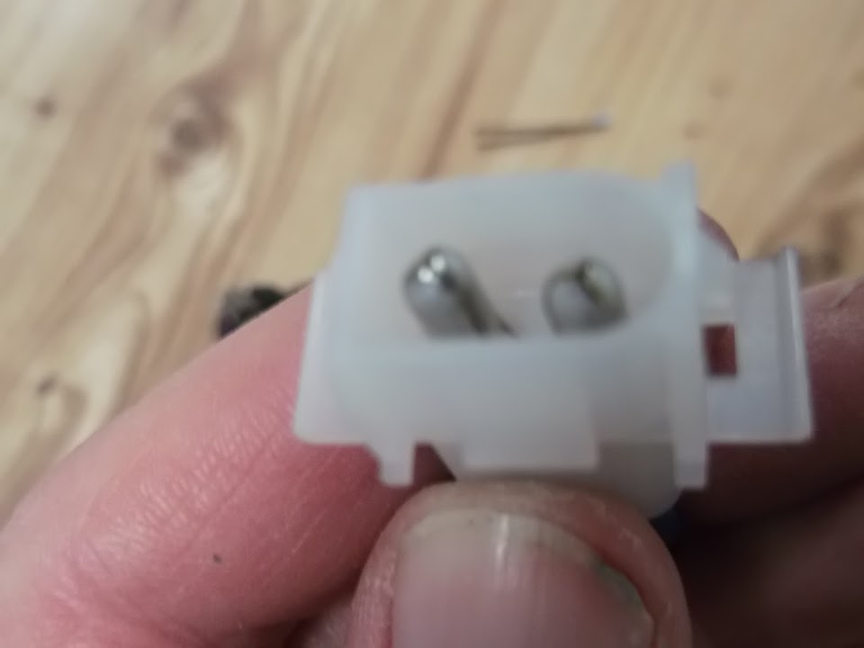
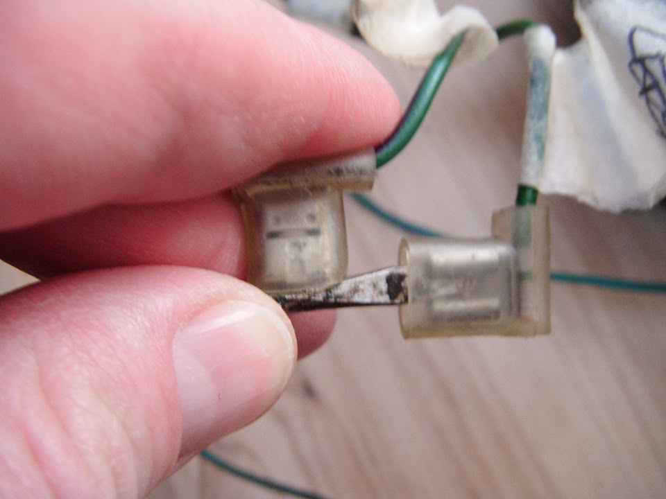
But when I went to swap the bulb out on the faulty front indicator, the real problem came to light.
The live wire was no longer connected to the small "pad" the bulb pushes against when fitted. 

In order to confirm this was the root cause of all the problems, I just held the wires in place by hand.

I soldered the live wire back into place, remembering to put the spring back in position first.
( Excuse the poor photo. )

Then with everything connected back together, I could now get all four indicators and the hazard switch light to come on.

Plus the left & right indicators all worked as they should, including the dash board warning light.
I've got to say I was very happy to see this.

A new roll of PVC wiring loom wrap also arrived today.

So at some point I will finish off wrapping the loom, but that's all for now.
Take care, Paul.
|
18th February 2015, 15:36
|
|
Senior Member
|
|
Join Date: Apr 2014
Location: Midlands
Posts: 405
|
|
Good work! wiring is such a pain in the rear! great when it works but oh my tracking down a fault can be very tedious indeed, a great amount of patience is required. I did up an MGB and when I bought it NONE of the wires made it from point to point without a change in colour and some bodged soldering.
|
|
Currently Active Users Viewing This Thread: 4 (0 members and 4 guests)
|
|
|
 Posting Rules
|
You may not post new threads
You may not post replies
You may not post attachments
You may not edit your posts
HTML code is Off
|
|
|
All times are GMT +0. The time now is 11:14.
|


 Linear Mode

