|
|
| Sammio Builds and discussions Sammio bodied car builds and specials |

18th February 2015, 21:44
|
 |
Senior Member
|
|
Join Date: Dec 2013
Posts: 839
|
|
Mr TYour thoughts are correct for the positioning of the thermostatic switch it is at the bottom and not at the top as i originally quoted so only need to find out the ideal on and off temperatures.
Cheers for that one Mr T.
Last edited by swifty; 24th February 2015 at 18:02..
|
18th February 2015, 22:24
|
|
Senior Member
|
|
Join Date: Dec 2013
Location: Sunny Cumbria
Posts: 470
|
|
The Kenlow Fan that came with my V8 Berlinetta that I am restoring came with an adjustable thermostat, can be dash mounted I think.
I haven't really looked at it yet, the thermostat has a capillary tube with a very slim bulb at the end which you insert into a hose of choice, thanks to Mister Towed's suggestion I will insert it into one of the bottom hose joints.
|
19th February 2015, 18:45
|
|
Senior Member
|
|
Join Date: Dec 2013
Posts: 839
|
|
Found some useful information today on fitting the correct temperature range thermostatic switch. It looks like you start with a switch with an ON temperature a couple of degrees above the thermostat fully open temperature which is either 82 or 88 to start with and if the fan runs regularly then you fit a slightly higher ON temp switch, its better to start low then increase if needs be to prevent overheating. If the bottom hose is colder than your target engine temperature then it will still cool the engine.
I suppose another solution would be to fit the variable thermostat as 8 valve ed has opted for but what ever system is installed don't forget to switch the supply voltage to the fan via a relay.
I hope to have the radiator installed this weekend all been well.
|
20th February 2015, 08:56
|
 |
Senior Member
|
|
Join Date: Feb 2012
Location: Wembley, London
Posts: 5,056
|
|
Quote:
Originally Posted by Mister Towed

...I can't quite remember what on-off temperatures my fan switch has, I'm sure it's on my build thread/on the road thread somewhere though.
|
I've just found that part of your build while looking for something else...
Quote:
Originally Posted by Mister Towed
...I've also replaced the adjustable thermostatic fan switch with a fixed one, which is much simpler and neater -
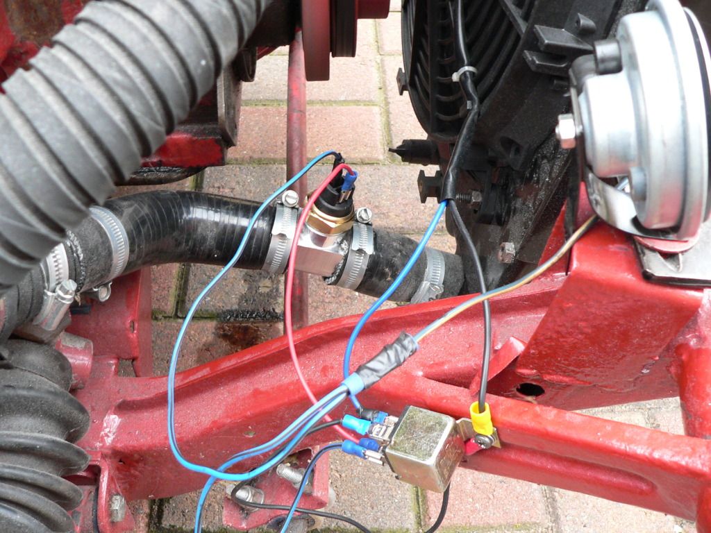
I've gone for an 'on at 88 off at 79' switch and mounted it in the bottom hose. This now cuts the fan in at the right moment, just as the needle climbs out from between the two dots on the temperature gauge, has it back between the dots in thirty seconds and then cuts out. Perfect. I'd say that you'd need a hotter switch if you plan to put it in the top hose though, as the water coming out of the block will be hotter than the water coming out of the radiator... |
|
20th February 2015, 16:55
|
|
Senior Member
|
|
Join Date: Dec 2013
Posts: 839
|
|
Cheers Paul i am going to try the 88 ON 79 OFF first and see how that preforms.
|
22nd February 2015, 20:56
|
|
Senior Member
|
|
Join Date: Dec 2013
Posts: 839
|
|

Decided to start fabricating the bulk head ally work.
The bulk head edge that the bonnet sits on has been built up to 30mm wide and the correct height so that the bonnet is flush when closed with the bulk head once the rubber seal is fitted.
IMG_5150.jpg
The next step was to fill the vertical uneven surface with fiber filler where the remote brake and clutch reservoirs will be fitted, the rest of the surface was built up with expanding foam so the ally sheet has something to fit against.
IMG_5156.jpg IMG_5142.jpg
The second image is before filling, you can see by how much the original surface curved inwards which would not be a good surface to try and fit 1mm ally sheet to.
IMG_5158.jpg IMG_5157.jpg
The back plate is pop riveted through the original fiber glass and is made from 1mm ally sheet as it very easy to cut and work with while the base plate is 3mm ally sheet to give a good surface for the various parts to be bolted too.
I made a few lengths of angle from 1mm ally 20mm x 20mm to finish the edges,.

|
24th February 2015, 17:39
|
|
Senior Member
|
|
Join Date: Dec 2013
Posts: 839
|
|
The remote reservoirs for the brake and clutch master cylinders arrived so decided to fabricate a bracket to mount them together on the bulk head.
IMG_5152.jpg
Made from 2mm ally sheet, the holes are purposely off center so that the plastic reservoirs sit centrally to the bracket.
IMG_5154.jpg
Reservoirs fitted, had to machine the pipe outlet fitting's to suit a push on pipe as they came threaded to screw directly into the master cylinder.
IMG_5155.jpg
Also machined a couple of 7/16 UNF ally pipe fittings for the master cylinder inlet, will use a dowty seal between the fitting and master cylinder body.
IMG_5151.jpg
Made a couple of stainless clevis pins for the master cylinders.
Well that's it for now see you all soon.
Last edited by swifty; 24th February 2015 at 18:00..
|
24th February 2015, 18:08
|
|
Senior Member
|
|
Join Date: Jan 2015
Posts: 168
|
|
Are you sure the 2mm ally bracket is strong enough?I had made them of 4mm and they started to crack due to vibration.
Now made them of 4mm stainless.........
http://www.rodsnsods.co.uk/forum/gar...a-66837/page47 |
24th February 2015, 18:15
|
|
Senior Member
|
|
Join Date: Dec 2013
Posts: 839
|
|
I made the brackets from a soft malleable grade ally which was heated to relive the stresses, thanks for the info so will keep an eye on them once on the road and if they do show signs of metal fatigue then stainless it will be or maybe it requires a couple of webs welding in place.
I did consider stainless but took the easy option of fabricating from ally but may of given myself extra work in the future.
Neat work with the ally reservoirs (just checked your link out), did you do this yourself?
Cheers again.
Last edited by swifty; 24th February 2015 at 18:19..
|
24th February 2015, 19:31
|
|
Senior Member
|
|
Join Date: Jan 2015
Posts: 168
|
|
Yes,made them on the lathe from a nice piece of solid ally.
Did'nt like the plastic Jampots which came with the MC.
Ofcourse mine are much heavier as yours so your bracket can be strong enough.
Perhaps a diagonal brace underneath will keep the vibrations out.
René
|
24th February 2015, 21:20
|
|
Senior Member
|
|
Join Date: Feb 2012
Location: Wembley, London
Posts: 5,056
|
|
Swifty - Your list of bespoke parts really takes this build into a league of its own. 
Keep up the great work, Paul. 
|
8th March 2015, 18:49
|
|
Senior Member
|
|
Join Date: Dec 2013
Posts: 839
|
|
Not a great deal accomplished over the past few weeks as i have been concentrating on the body filling in all the imperfections and trying to get the curves smooth.
Fitted the ally rad which is over twice the size of the original.
IMG_5167.jpg
Fabricated two mount brackets to hold the rad in place.
Modified the thermostatic housing so that the feed to the top of the rad is now in the correct position, originally it was pointing to the front of the car now its sweeps around the rocker box which will take the pipe around the back of the alternator.
IMG_5165.jpg
Tig welded the ally housing.
IMG_5161.jpg
Progressed the bulk head lining with 3mm ally sheet, made the cut outs for the tyres to clear when on full lock.
IMG_5163.jpg
Made a box for the master cylinders to clear the bulk head the only problem now is the fitting for the pipe from the remote reservoir is very close to the bulk head.
Has any body come across a 45 or 90 degree fitting that would allow the feed pipe to clear the top of the bulk head.
Well that's it for now see you all soon.
Last edited by swifty; 8th March 2015 at 21:47..
|
8th March 2015, 21:28
|
|
Senior Member
|
|
Join Date: Dec 2013
Posts: 839
|
|
It looks like a banjo fitting and bolt is the solution for the limited access to the master cylinder feed pipe connection, basically something like this.
banjo.jpg
The only difference is i need a pipe push fit rather than a screw fit on the banjo fitting itself.
Will hopefully have a couple made this week out of stainless steel.
|
9th March 2015, 07:00
|
|
Senior Member
|
|
Join Date: Feb 2012
Location: Wembley, London
Posts: 5,056
|
|
Swifty - Your whole engine bay area is going to look amazing when you flip the bonnet up.
I don't envy all the time and effort you must have put into the body work. 
I fully expect your car to look like it has just left a factory production line when it is finsihed.
Whereas mine will look like it was written off & bashed back into shape by a dodgy back street garage. 
Good luck, Paul.
|
12th March 2015, 20:03
|
|
Senior Member
|
|
Join Date: Dec 2013
Posts: 839
|
|
Cheers Paul.
Finished off the two stainless steel banjo fittings with 7/16 unf thread to suit the master cylinders and four copper washers. The pipe tails were tig welded.
IMG_5169.jpg IMG_5171.jpg
Ive tried them in place and they will work so i need to finish the bulkhead fabrication then mount master cylinders and reservoirs to bleed both the brakes and clutch.
Today i spoke to a local plastics company who have the facility to profile the screen from makrolon but i think as i am not 100% sure of the final shape i'll buy an uncut sheet and work from there, one advantage of profiling is the neat polished edge but i am sure i will be able to polish the edge once i have the shape I'm happy with.
Well that's it for now see you all soon.
|
14th March 2015, 17:23
|
|
Senior Member
|
|
Join Date: Dec 2013
Posts: 839
|
|
I originally had a gauze filter fitted to the rocker box vent but after reading various posts about oily smells i decided to fit an oil catch tank which will be piped between the rocker box and inlet manifold.
Looked around to buy one then decided to make a one off special tank out of ally.
IMG_5178.jpg
Its made from a main body bored out with various tapped holes and a machined slot fitted with a glass view window to check the oil level for future maintenance.
Both lids have eight holes on a pcd matching the holes in the body, the lid has a center hole tapped out to 7/16 unf for the tube tail to screw into and the bottom cover will have a center hole tapped to match a drain tap or plug once i find a suitable part.
IMG_5175.jpg
This part is the lid with the separation tube and steel gauze fitted between two drilled ally discs, the open ended tube sits about 10mm off the bottom cover with two 5mm dia through holes.
IMG_5180.jpg IMG_5183.jpg
Both the top and bottom covers are sealed by an o ring which sits in a groove, the o ring then clamps down onto a 45 degree taper as shown in the second photo.
IMG_5174.jpg
Oil catch tank assembled with 8mm pipe tails and mounting bracket tig welded to the body.
Well that's it for now see you all soon.
Last edited by swifty; 16th March 2015 at 18:59..
|
14th March 2015, 19:45
|
|
Senior Member
|
|
Join Date: Dec 2013
Location: thurcroft, Rotherham South Yorkshire
Posts: 196
|
|
lovely piece of engineering, I take my hat of to you sir.
|
14th March 2015, 21:12
|
|
Senior Member
|
|
Join Date: Jun 2011
Location: birchington, kent
Posts: 1,769
|
|
I would have been disappointed if you had bought it...
|
15th March 2015, 17:58
|
|
Senior Member
|
|
Join Date: Feb 2012
Location: Wembley, London
Posts: 5,056
|
|
Swifty - It really is a joy to see not only what you can make, but the extremely high standard of construction too.
Good luck, Paul.
|
16th March 2015, 19:06
|
|
Senior Member
|
|
Join Date: Dec 2013
Posts: 839
|
|
Thurcroft flyer, garyh and Paul Thanks for the comments.
A question about piping in an ally rad with a header tank.
Am i correct in thinking the return to the header tank (top pipe) comes from the thermostat top cover outlet and the header tank outlet (bottom pipe) is piped into the steel pipe that runs under the carburetors returning back to the water pump.
I have read that the flow into the header tank may be to high so a re-stricter is fitted to the return to slow the flow down otherwise the cooling system will not run efficiently, has anybody come across this.
|
|
Currently Active Users Viewing This Thread: 1 (0 members and 1 guests)
|
|
|
 Posting Rules
|
You may not post new threads
You may not post replies
You may not post attachments
You may not edit your posts
HTML code is Off
|
|
|
All times are GMT +0. The time now is 22:49.
|


 Linear Mode

