|
|
| Vintage and Classic Roadster Kit Car Builds For Vintage and Classic era kit cars. Post your build reports, problems and progress here |

15th August 2019, 12:26
|
|
Member
|
|
Join Date: Dec 2016
Posts: 53
|
|
Quote:
Originally Posted by peterux

I've not tested it yet but I'm very happy with progress this week
|
Looks great, hope it does work, never seems to go back as nice the 2nd time |
21st August 2019, 19:25
|
 |
Senior Member
Enthusiast
|
|
Join Date: Mar 2005
Posts: 3,079
|
|
 A few more tasks....
Molleur, Amir and Pheaton......Many thanks for all the kind remarks.
---------------------------------------------------------------------------
Moving on........ I've manged to complete some more items on my task list.
First up brakes. I had refitted the the brake master cylinder and filled the system with brake fluid a few weeks ago and I was very disappointed to immediately find brake fluid dripping on the garage floor.
One joint was a simple mistake as it was only hand tight and I had just forgotten to tighten it up. The second one took a closer inspection where I found the pipe was not properly aligned with the fitting meaning the flared pipe was not sealing correctly.
With both of these fixed I was able to bleed the whole system. I'm not yet 100% happy that all the air is out but I'll leave it a few weeks to settle and then bleed it again. I also need to crawl around under the car to fully check for any other leaks.
I was then able to fit the brake fluid level switch cable.
 Brake fluid level switch Brake fluid level switch by Sabrebuilder, on Flickr
The brake fluid level switch is wired in with the handbrake switch. I have no idea why the Ford designers made the connector so large?
I then had to route the cable to the handbrake switch so it made sense to route the window switch cables at the same time.
 Window switch cables Window switch cables by Sabrebuilder, on Flickr
The electric window switches will be mounted on the gearbox tunnel. These cables will be hidden under the carpets.
I had to spend a while on my back with my head in the footwell to cable tie these cables. I just hope the IVA man appreciates my efforts.
 Cabling Cabling by Sabrebuilder, on Flickr
I then cleaned up and greased the handbrake mechanism and then used a 5mm thick strip of foam rubber to seal it to the propshaft tunnel. The gaps left over from when I modified the gearbox and propshaft tunnels were filled with some small pieces of water resistant mdf.
 Handbrake refitted Handbrake refitted by Sabrebuilder, on Flickr
The handbrake was connected to cable 'half-moon' and liberally coated with white grease.
 Handbrake cable Handbrake cable by Sabrebuilder, on Flickr
With most of the engine related wiring now complete I then moved back to the engine bay and fitting the scuttle cover. My first attempt at re-fitting the scuttle cover failed when I discovered it fouled on the wiper motor. I hadn't realised how critical the position of the motor is. In the end it took three attempts to get the right position. Very frustrating 
 Wiper motor position Wiper motor position by Sabrebuilder, on Flickr
With the motor moved I could then temporarily fit the cover.
 Scuttle cover Scuttle cover by Sabrebuilder, on Flickr
I then gave it three coats of Autoglym polish before covering it with paper towel to prevent damage.
 Scuttle cover Scuttle cover by Sabrebuilder, on Flickr
So some good progress this week and next I'll be making up some brackets to mount the cooling system header tank.
...peter

|
13th August 2019, 20:53
|
|
Senior Member
|
|
Join Date: Jun 2015
Posts: 1,401
|
|
Neatly done. Looking great!
|
15th August 2019, 12:14
|
|
Member
|
|
Join Date: Jul 2014
Location: Ealing London
Posts: 54
|
|
 A well done job
Peter, a well done job is an under statement. I think every step you take in the build of this bespoke car is well thought of and meticulously executed.
|
22nd August 2019, 05:45
|
|
Member
|
|
Join Date: Dec 2016
Posts: 53
|
|
Forum needs to instal a 'Like' system, I don't really want to comment but still give you encouragement of your brilliant work.
|
22nd August 2019, 08:03
|
|
Member
|
|
Join Date: Jul 2014
Location: Ealing London
Posts: 54
|
|
It is always a pleasure to see a wonderful work done and confirm the fact.
|
22nd August 2019, 09:23
|
|
Senior Member
|
|
Join Date: Nov 2017
Posts: 109
|
|
|
28th August 2019, 20:07
|
|
Senior Member
Enthusiast
|
|
Join Date: Mar 2005
Posts: 3,079
|
|
A small setback....
Pheaton, Amir and Kon thanks for the 'likes'.
--------------------------------------------------------------
I had a small setback this week.........
I opened the garage door to find a small puddle of power steering fluid on the concrete. My recon steering rack is leaking fluid. 
I assume the seals have dried out and shrunk or possibly the seals have been damaged by turning the steering without any fluid. With hindsight (that wonderful thing!) I think I should have found a way of keeping the rack full of fluid.
 Steering rack leak Steering rack leak by Sabrebuilder, on Flickr
The leak seems to be coming from this 'dust' cap.
 Steering rack leak Steering rack leak by Sabrebuilder, on Flickr
I have another used rack that I may try or get recon'd.
 Steering rack leak Steering rack leak by Sabrebuilder, on Flickr
But I have decided to leave it for now and worry about it nearer to the IVA test.
So moving on with some more progress....
My plan was to mount the cooling system header tank something like this.....
 Coolant Header Tank Coolant Header Tank by Sabrebuilder, on Flickr
But that was two years ago and before I had fully worked out the heater hoses and the outlet clashed directly with the heater control valve.
But I found that rotating the tank through 180 degrees meant the outlet cleared the heater hoses but made making the mounting brackets a bit more challenging. Here I am checking the tank clears the bonnet represented by the piece of wood.
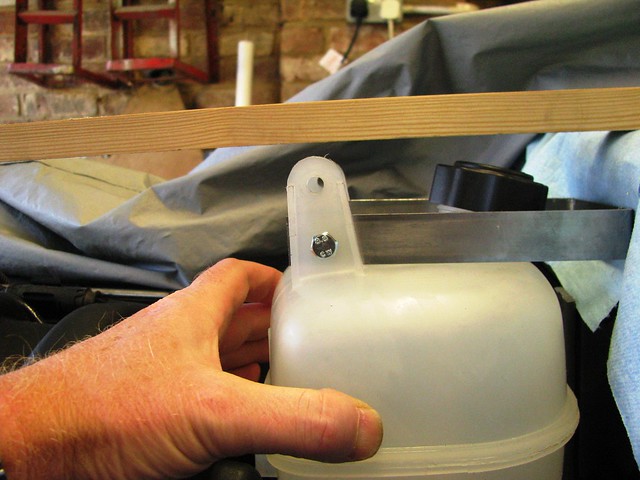 Header Tank Header Tank by Sabrebuilder, on Flickr
Here is the top bracket finished and bolted to the scuttle cover. I put a strengthening plate on the inside of the cover.
 Header Tank Header Tank by Sabrebuilder, on Flickr
The lower bracket was made from 4mm thick steel strip to support the weight of the tank and coolant. Again, a support plate was mounted on the inside of the cover to strengthen it.
 Header Tank Header Tank by Sabrebuilder, on Flickr
And here it is finished.
 Header Tank Header Tank by Sabrebuilder, on Flickr
Next it was on to the Idle Control Valve (ICV) hose....
Because the inlet bellows to the throttle body is upside down (compared to the way BMW designed it) I needed to find a way of feeding the idle air from the inlet bellows to the ICV that is mounted under the inlet manifold. I used silicone hose and Mikalor wire hose clamps. These are much cheaper than Jubilee clips, neater and so much faster to install.
 ICV hose ICV hose by Sabrebuilder, on Flickr
The hose drops down the gap between the throttle body bellows and the inlet manifold and then through a 180 degree elbow up into the ICV.
 ICV hose ICV hose by Sabrebuilder, on Flickr
It was then on to the brake servo vacuum hose with a new length of pucker BMW hose.
 Brake Servo Vacuum hose Brake Servo Vacuum hose by Sabrebuilder, on Flickr
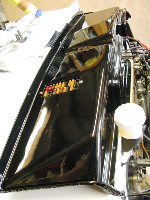
So that's the progress this week and I'll leave you with this photo.....
 August 2019 view August 2019 view by Sabrebuilder, on Flickr
To check the clearance of the header tank I temporarily installed the radiator cover.
I couldn't resist taking this shot and doesn't that BMW straight 6 engine suit the Sabre! 
Next week I shall be working on mounting the radiator......
....peter
|
11th September 2019, 19:40
|
|
Senior Member
Enthusiast
|
|
Join Date: Mar 2005
Posts: 3,079
|
|
Not a lot.....
I've not had much time over the last two weeks so just a few tasks completed.
I've finished the servo vaccum hose with a reducing elbow.
 Servo Vacuum Hose Servo Vacuum Hose by Sabrebuilder, on Flickr
All hoses are supported with cable ties separated by small off cuts of fuel hose.
I could then complete the Mass Air Flow meter and air filter final installation. One more hose clip (on order) to be added and MAF cable needs to be properly secured.
 MAF and Air Filter MAF and Air Filter by Sabrebuilder, on Flickr
Then, after de-rusting and painting, I've refitted the radiator support frame.
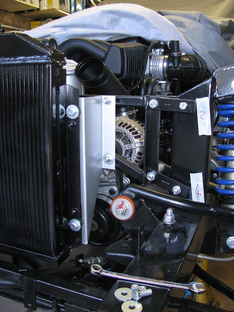 Radiator Frame Radiator Frame by Sabrebuilder, on Flickr
And then refitted the radiator......
 Radiator Radiator by Sabrebuilder, on Flickr
I didn't want the ali radiator to show through the radiator grill so I gave a quick thin coat of VHT paint. It needs a second coat before final fixing, but I ran out of paint.
Next tasks include fitting the radiator hoses and wiring up the radiator fan, etc.
Well that's all for now........
............peter |
12th September 2019, 06:19
|
|
Member
|
|
Join Date: Jul 2014
Location: Ealing London
Posts: 54
|
|
 Thinking way ahead
Well done Peter, It won't be long before you'll be able to enjoy your hand crafted master piece.
|
24th September 2019, 05:23
|
 |
Senior Member
|
|
Join Date: Feb 2012
Location: Wembley, London
Posts: 5,058
|
|
Looking like you are getting closer to firing up the engine. 
Good luck, Paul.  |
19th October 2019, 22:10
|
|
Senior Member
|
|
Join Date: Jun 2015
Posts: 1,401
|
|
I know how that feels. One day you are the dog, and the next a lamp post.
|
20th October 2019, 10:06
|
 |
Senior Member
|
|
Join Date: Nov 2011
Location: Exeter
Posts: 187
|
|
Copper washers
I have had problems recently with copper washers on brake lines not sealing properly. The first instance was a classic car banjo connection to the rear brake cylinder. The second instance was the Goodridge banjo connections on the front calipers on my Marlin Hunter / Cabrio.
Not all copper washers are the same! I had used after market ones that were in a multi pack from a well known local parts shop. These are too thin and the outer diameter is too large. The result is that they are too strong and do not deform (crush) enough, hence the leakage. This is especially important for the Goodridge banjos which have a raised ridge to assist the seal. Another factor affecting “crushability” is the hardness of the copper. The thin ones seem quite hard whereas the Goodridge ones are softer and the copper is a more pinky annealed colour.
Attached photo shows both types of washer. The correct Goodridge one is on the right.
The Goodridge ones were obtained from Demon Tweeks, link below:-
https://www.demon-tweeks.com/uk/good...washers-243438
Also available from Merlin Motorsport
https://www.merlinmotorsport.co.uk/p...1-8bsp-g-44516
A final comment is that these washers should never be reused. Fit new every time the joint is separated.
Meantime keep up the good work. The high standard is a credit to you. Peter. |
20th October 2019, 15:55
|
|
Senior Member
Enthusiast
|
|
Join Date: Mar 2005
Posts: 3,079
|
|
Thanks Peter for the feedback on copper washers.
Those Goodridge seals do look nice and thick. The originals I used were the ones that came with my Goodridge SS braided hoses but I don't think they were as thick as those.
Even though I have now refitted the hoses again with two soft cooper seals (supplied by HEL Performance) I'm now thinking that this is the wrong approach on these calipers. The area around the threaded hole has not been machined flat and is just the rough casting finish suggesting the seal should at the bottom of hole. But the Goodridge hose fitting is the wrong shape to seal with the concave seat in the caliper and being Stainless Steel it doesn't deform when tightened up.
Looking back at my dismantling photos I can see the original builder used traditional rubber brake hoses which were simply screwed into the caliper without a copper crush washer.
 Front brakes, hubs, etc Front brakes, hubs, etc by Sabrebuilder, on Flickr
EDIT: This is the wrong photo, please see post #408 below
A bit of a retrograde step but i'm thinking of reverting back to rubber hoses. 
Last edited by peterux; 21st October 2019 at 09:12..
Reason: wrong photo posted
|
20th October 2019, 20:19
|
|
Senior Member
|
|
Join Date: Nov 2011
Location: Exeter
Posts: 187
|
|
It would be a shame to go back to rubber hoses as the Goodridge braided hoses are so much better and give a really firm pedal feel.
As you say, for the copper washers to work there should be a spot faced area around the threaded hole, not a rough cast surface. Those calipers and front hubs look like the Ford Sierra brakes that I am currently overhauling on my Marlin Hunter. The cast round boss on mine is for the bleed nipple that is designed to seal on the angled face at the bottom of the hole. The copper washer and banjo fitting on mine are on the spot faced lug on the square angled boss that projects from the end of the caliper piston. Just a thought but have your connections been reversed in error? The angled spot faced boss should face inwards and upwards. The bleed nipple is above this and facing upwards and angled towards the rear. You may have to separate the calipers from the support brackets and swap the calipers to the other side of the car and turn them up the other way to achieve this. The support brackets are handed so should be fitted on the correct side of the car. As mine is stripped down at present I can post photos to clarify this if it helps. Peter.
|
20th October 2019, 20:41
|
|
Senior Member
|
|
Join Date: Nov 2011
Location: Exeter
Posts: 187
|
|
This photo shows my off side caliper. Peter.
|
21st October 2019, 09:09
|
|
Senior Member
Enthusiast
|
|
Join Date: Mar 2005
Posts: 3,079
|
|
Hi Peter,
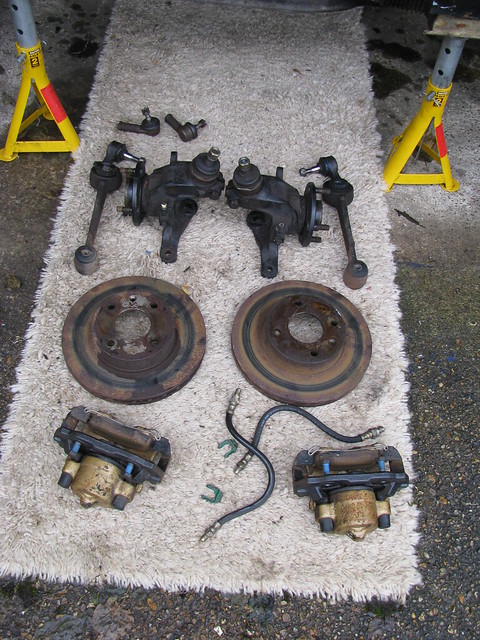
thanks again for your suggestions but I think I have confused matters by posting the wrong picture above. It should have been a picture of my rear brakes which is where I'm having the issues.
Here is the correct picture......
 Parts removed today Parts removed today by Sabrebuilder, on Flickr
Sorry for wasting your time. |
21st October 2019, 20:40
|
|
Senior Member
|
|
Join Date: Nov 2011
Location: Exeter
Posts: 187
|
|
No problem. Others on the forum may find the photos useful anyway.
Once the front brake overhaul is finished (too many interruptions lately!) I will be working on the rears, so in a couple of days I will check and photo my rear calipers. Peter.
|
25th October 2019, 14:15
|
|
Senior Member
|
|
Join Date: Nov 2011
Location: Exeter
Posts: 187
|
|
Attached photos show my near side rear caliper brake pipe connection. Hope they help.
I have never taken this joint apart on my car so I can’t comment on the type of sealing method. However I have a feeling that there shouldn’t be a washer present, especially if clamping against an uneven cast surface. Without the washer the hose union would normally seal at the bottom of the hole.
Check what the seal surface at the bottom of the hole looks like. From the hoses you have I would expect it to be a concave conical surface. However I have seen fittings where the bottom of the hole has a raised conical surface. That is normally designed to mate up with a double flared brake line, clamped in place with a pipe nut. Peter.
|
26th October 2019, 19:14
|
|
Senior Member
Enthusiast
|
|
Join Date: Mar 2005
Posts: 3,079
|
|
Thanks for the photo's.
I have bought some Borg and Beck traditional hoses. Here are some comparison photo's.
 Goodridge v. Borg and Beck hoses Goodridge v. Borg and Beck hoses by Sabrebuilder, on Flickr
 Goodridge v. Borg and Beck hoses Goodridge v. Borg and Beck hoses by Sabrebuilder, on Flickr
And they are clearly not designed to use copper washers.....
 Borg and Beck brake hose Borg and Beck brake hose by Sabrebuilder, on Flickr
When you tighten them up you can feel them deform and create a good seal. No leaks so far!
With hindsight I'm thinking that it was actually the copper washer that was preventing the original Goodridge hoses sealing properly.
On my front calipers I did not fit copper washers and no leaks.
Last edited by peterux; 26th October 2019 at 19:15..
Reason: reworded last sentence
|
|
Currently Active Users Viewing This Thread: 2096 (0 members and 2096 guests)
|
|
|
 Posting Rules
|
You may not post new threads
You may not post replies
You may not post attachments
You may not edit your posts
HTML code is Off
|
|
|
All times are GMT +0. The time now is 00:36.
|


 Hybrid Mode
